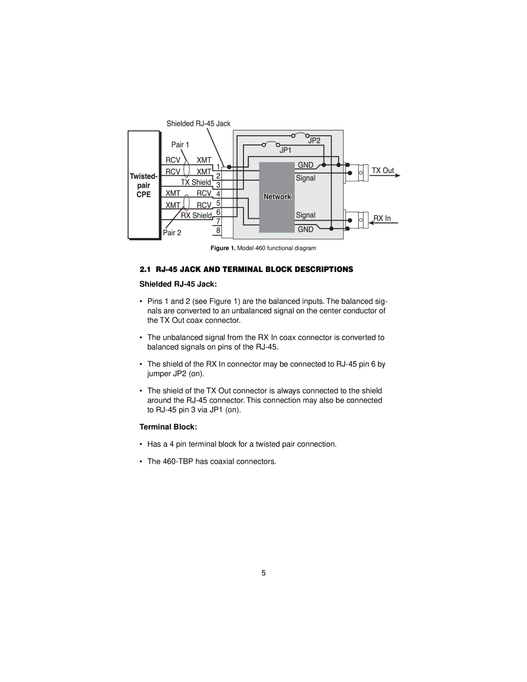
Figure 1. Model 460 functional diagram
2.1 RJ-45 JACK AND TERMINAL BLOCK DESCRIPTIONS
Shielded RJ-45 Jack:
•Pins 1 and 2 (see Figure 1) are the balanced inputs. The balanced sig- nals are converted to an unbalanced signal on the center conductor of the TX Out coax connector.
•The unbalanced signal from the RX In coax connector is converted to balanced signals on pins of the
•The shield of the RX In connector may be connected to
•The shield of the TX Out connector is always connected to the shield around the
Terminal Block:
•Has a 4 pin terminal block for a twisted pair connection.
•The
5
