SECTION 10: WIRING
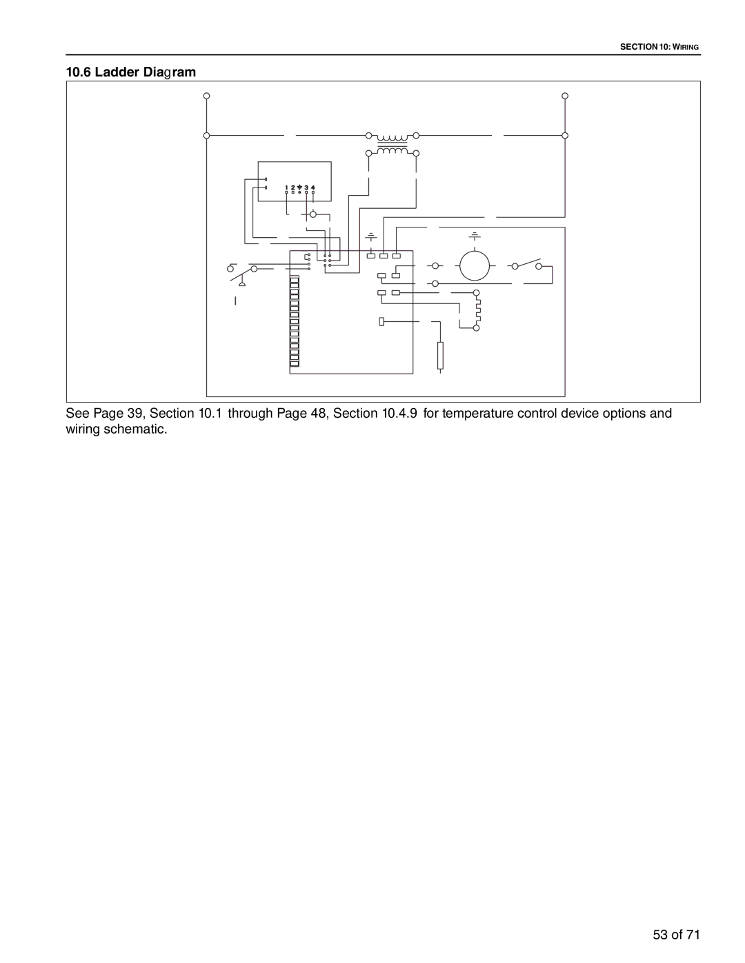
10.6 Ladder Diagram
L1 |
|
|
|
| L2 |
BLK |
| 120V |
|
| WHT |
|
|
|
| ||
|
| 24V |
|
|
|
GAS VALVE | YEL | BLU |
|
|
|
|
|
|
| ||
|
|
|
|
| |
BRN |
|
|
|
|
|
BRN |
|
|
|
| WHT |
|
|
|
|
| |
PRP | BRN | BLK |
|
|
|
|
|
|
|
| |
ORG |
|
|
|
| DOOR |
BLU | GRN |
|
| GRN | |
BLU |
|
|
|
| SWITCH |
|
|
|
|
| |
BLU |
| BLU | BLK | MOTOR | BLK |
BLU |
|
|
|
|
|
|
| BLU |
|
| BLK |
AIR SWITCH |
|
| WHT |
| HOT |
|
|
|
|
| |
| CONTROL |
|
|
| SURFACE |
|
|
| WHT | IGNITER | |
|
|
|
| ||
|
| BLK |
|
|
|
|
|
| FLAME |
| |
|
|
| SENSOR |
| |
See Page 39, Section 10.1 through Page 48, Section 10.4.9 for temperature control device options and wiring schematic.
53 of 71
