SECTION 10: WIRING
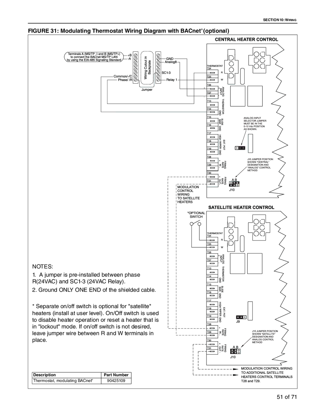
FIGURE 31: Modulating Thermostat Wiring Diagram with BACnet® (optional)
NOTES: |
|
1. A jumper is | |
R(24VAC) and | |
2. Ground ONLY ONE END of the shielded cable. | |
* Separate on/off switch is optional for "satellite" | |
heaters (install at user level). On/Off switch is used | |
to disable heater operation or reset a heater that is | |
in "lockout" mode. If on/off switch is not desired, | |
leave jumper wire between R and W terminals in | |
place. |
|
Description | Part Number |
Thermostat, modulating BACnet® | 90425109 |
| 51 of 71 |