10.4.7 Cable Termination
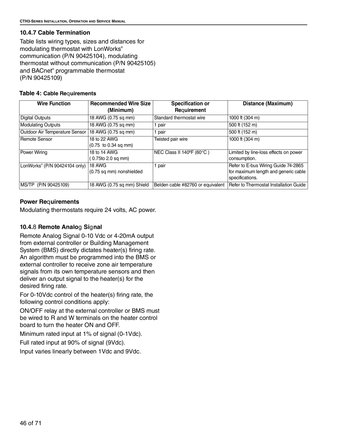
Table lists wiring types, sizes and distances for modulating thermostat with LonWorks® communication (P/N 90425104), modulating thermostat without communication (P/N 90425105) and BACnet® programmable thermostat
(P/N 90425109)
Table 4: Cable Requirements
Wire Function | Recommended Wire Size | Specification or | Distance (Maximum) | |
|
| (Minimum) | Requirement |
|
|
|
|
|
|
Digital Outputs | 18 | AWG (0.75 sq mm) | Standard thermostat wire | 1000 ft (304 m) |
|
|
|
|
|
Modulating Outputs | 18 | AWG (0.75 sq mm) | 1 pair | 500 ft (152 m) |
|
|
|
|
|
Outdoor Air Temperature Sensor | 18 | AWG (0.75 sq mm) | 1 pair | 500 ft (152 m) |
|
|
|
| |
Remote Sensor | 18 to 22 AWG | Twisted pair wire | 1000 ft (304 m) | |
| (0.75 to 0.34 sq mm) |
|
| |
|
|
|
| |
Power Wiring | 18 to 14 AWG | NEC Class II 140ºF (60°C ) | Limited by | |
| ( 0.75to 2.0 sq mm) |
| consumption. | |
|
|
|
|
|
LonWorks® (P/N 90424104 only) | 18 | AWG | 1 pair | Refer to |
| (0.75 sq mm) nonshielded |
| for maximum length and generic cable | |
|
|
|
| specifications. |
|
|
|
|
|
MS/TP (P/N 90425109) | 18 | AWG (0.75 sq mm) Shield | Belden cable #82760 or equivalent | Refer to Thermostat Installation Guide |
|
|
|
|
|
Power Requirements
Modulating thermostats require 24 volts, AC power.
10.4.8 Remote Analog Signal
Remote Analog Signal
For
ON/OFF relay at the external controller or BMS must be wired to R and W terminals on the heater control board to turn the heater ON and OFF.
Minimum rated input at 1% of signal
Full rated input at 90% of signal (9Vdc).
Input varies linearly between 1Vdc and 9Vdc.
46 of 71