SECTION 10: WIRING
For
ON/OFF relay at the external controller or BMS must be wired to R and W terminals on the heater control board to turn the heater ON and OFF.
(Open Circuit = OFF, Closed Circuit = ON). Minimum rated input at 1% of signal
BMS controllers often offer PID loop control that can optimize output signal and rate of change of the output signal. Common analog application is defined as follows:
1.BMS sensors that monitor zone air
temperatures are located in the heating space.
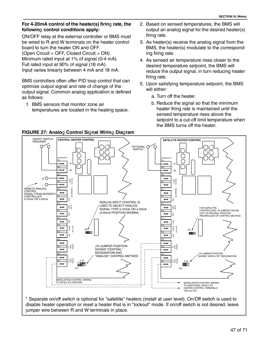
FIGURE 27: Analog Control Signal Wiring Diagram
2.Based on sensed temperatures, the BMS will
output an analog signal for the desired heater(s) firing rate.
3.As heater(s) receive the analog signal from the BMS, the heater(s) modulate to the correspond- ing firing rate.
4.As sensed air temperature rises closer to the desired temperature setpoint, the BMS will reduce the output signal, in turn reducing heater firing rate.
5.Upon satisfying temperature setpoint, the BMS will either:
a.Turn off the heater.
b.Reduce the signal so that the minimum heater firing rate is maintained until the sensed temperature rises above the setpoint to a
ON/OFF SWITCH | CENTRAL HEATER CONTROL |
REQUIRED |
|
| *OPTIONAL |
| SWITCH |
| THERMOSTAT |
| T24 |
| R |
| T25 |
| W |
SATELLITE HEATER CONTROL
THERMOSTAT
T24
R
T25
W
+ |
| T26 |
| INPUT + - |
| ANALOG |
|
|
|
|
|
|
|
|
|
|
|
|
|
|
|
|
|
|
|
|
|
|
|
|
|
| |||
|
|
|
|
|
|
|
|
|
|
|
|
|
|
| |||
|
| T27 |
|
|
|
|
|
|
|
|
|
|
|
|
| ||
- |
|
|
|
|
|
|
|
|
|
|
|
|
|
|
| ||
|
|
|
|
| THERMISTOR |
|
|
|
|
|
|
|
|
|
|
| |
REMOTE ANALOG | T13 |
|
|
|
|
|
|
|
|
|
|
|
|
|
| ||
CONTROL |
|
|
|
|
|
|
|
|
|
|
|
|
|
|
| ||
SIGNAL FROM SEPARATE |
|
|
|
|
|
|
|
|
|
|
|
|
|
|
| ||
|
|
|
|
|
|
|
|
|
|
|
|
|
|
| |||
CONTROLLER | T14 |
|
|
|
|
|
|
|
|
|
|
|
|
|
| ||
|
| GN |
|
|
|
|
|
|
|
|
|
|
|
|
| ||
|
| D |
|
|
|
|
|
|
|
|
|
|
| ANALOG INPUT CONTROL IS | |||
|
|
|
|
|
|
|
|
|
|
|
|
|
|
|
| ||
|
| T15 |
|
|
|
|
|
|
|
|
|
|
|
|
| ||
|
|
|
| BAR | SLIDE |
|
|
|
|
|
|
|
|
| USED TO SELECT ANALOG | ||
|
|
|
|
|
|
|
|
|
|
|
|
| SIGNAL TYPE | ||||
|
| T16 |
|
|
|
|
|
|
|
|
|
|
|
|
| ||
|
|
|
| GN |
|
|
|
|
|
|
|
|
|
|
| ||
|
|
|
| D |
|
|
|
|
|
|
|
|
|
|
|
|
|
|
| T17 |
|
|
|
|
|
|
|
|
|
|
|
|
|
|
|
|
|
|
| HIGH |
|
|
|
|
|
|
|
|
|
|
|
|
|
|
|
|
|
|
|
|
|
|
|
|
|
|
|
|
|
|
|
|
| T18 |
| WIPER |
| EXT. POT |
|
|
|
|
|
|
|
|
|
|
|
|
|
|
|
|
|
| J9 |
|
|
| |||||||
|
| T19 |
| GN |
|
|
|
|
|
|
|
|
|
|
|
| |
|
|
|
|
|
|
|
|
|
|
|
|
|
|
|
|
| |
|
|
|
| D |
|
|
|
|
|
|
|
|
|
|
|
|
|
|
| T28 |
|
|
|
|
|
|
|
|
|
|
|
|
|
|
|
|
|
|
| + |
| FIRING |
|
|
|
|
|
|
|
|
|
|
|
|
|
|
| RATE IN |
|
|
|
|
|
|
|
| J10 JUMPER POSITION | ||||
|
| T29 |
|
|
|
|
|
|
|
|
| ||||||
|
|
|
|
|
|
|
|
|
|
|
| SHOWS "CENTRAL" | |||||
|
|
|
| - |
|
|
|
|
|
|
|
|
|
| |||
|
|
|
|
|
|
|
|
|
|
|
|
|
|
| |||
|
|
|
|
|
|
|
|
|
|
|
|
|
|
| DESIGNATION AND | ||
|
|
|
|
|
|
|
|
|
|
|
|
|
|
| |||
T26
T27
T13
T14
T15
T16
T17
T18
T19
T28
T29
INPUT + - | ANALOG | |
GN |
| THERMISTOR |
|
| |
D |
|
|
BAR | SLIDE | |
GN |
|
|
D |
|
|
HIGH |
|
|
WIPER |
| EXT. POT |
GN |
|
|
D |
|
|
+ |
| FIRING |
IN | RATE | |
- |
|
|
J9
FOR SATELITTE
CONTROLLERS, J9 JUMPER CAN BE LEFT IN ORIGINAL POSITION REGARDLESS OF CONTROL METHOD.
| T30 |
|
|
|
|
|
|
| "ANALOG" CONTROL METHOD. | |
|
| + | RATE | FIRING |
|
|
|
| ||
|
| OUT |
| A B | ||||||
| T31 | |||||||||
|
|
|
|
|
|
|
| |||
|
| - |
|
|
|
|
|
|
|
|
|
|
|
|
|
|
|
|
|
| |
|
|
|
|
| J10 | |||||
|
|
|
|
| ||||||
|
|
|
|
|
|
|
| |||
MODULATION CONTROL WIRING | ||||||||||
TO SATELLITE HEATERS | ||||||||||
T30 |
|
|
|
| J10 JUMPER POSITION | ||
|
|
| + | FIRING |
|
| SHOWS "SATELLITE" DESIGNATION. |
|
|
|
|
|
| ||
|
|
| RATE OUT | A B | |||
T31 | |||||||
|
|
| - |
|
|
|
|
|
|
|
|
|
|
| |
|
|
|
|
|
|
|
|
J10
MODULATION CONTROL WIRING
TO ADDITIONAL SATELLITE
HEATER CONTROL TERMINALS
T28 and T29.
*Separate on/off switch is optional for "satellite" heaters (install at user level). On/Off switch is used to disable heater operation or reset a heater that is in "lockout" mode. If on/off switch is not desired, leave jumper wire between R and W terminals in place.
47 of 71