3.0 INSTALLATION
Patton's Model 552 is easy to install and should give you years of
1.Unplug (disconnect) the existing connection between the network cable and the equipment’s I/O port.
2.Install the Model 552 between the incoming network cable and the protected equipment using the 6 inch (15.2cm.) modular patch cable (supplied). Place the surge protector as close as possible to the device being protected.
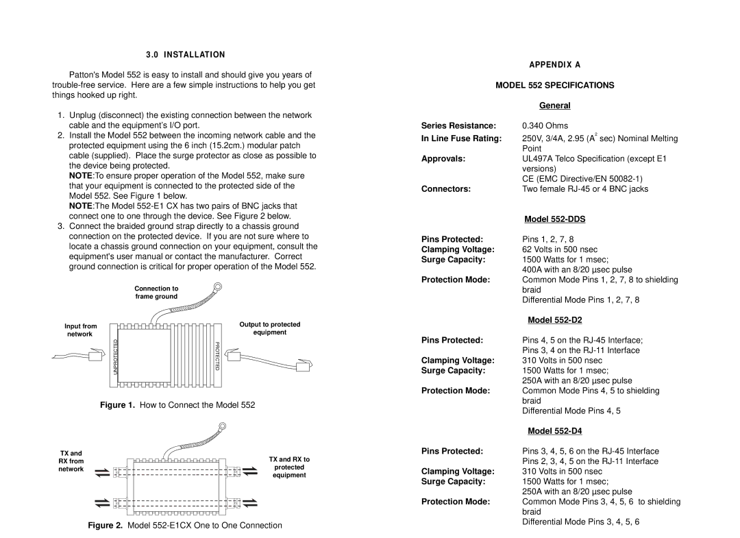
NOTE:To ensure proper operation of the Model 552, make sure that your equipment is connected to the protected side of the Model 552. See Figure 1 below.
NOTE:The Model
3.Connect the braided ground strap directly to a chassis ground connection on the protected device. If you are not sure where to locate a chassis ground connection on your equipment, consult the equipment's user manual or contact the manufacturer. Correct ground connection is critical for proper operation of the Model 552.
Connection to frame ground
APPENDIX A
MODEL 552 SPECIFICATIONS
| General |
Series Resistance: | 0.340 Ohms |
In Line Fuse Rating: | 250V, 3/4A, 2.95 (A2 sec) Nominal Melting |
| Point |
Approvals: | UL497A Telco Specification (except E1 |
| versions) |
| CE (EMC Directive/EN |
Connectors: | Two female |
| Model |
Pins Protected: | Pins 1, 2, 7, 8 |
Clamping Voltage: | 62 Volts in 500 nsec |
Surge Capacity: | 1500 Watts for 1 msec; |
| 400A with an 8/20 µsec pulse |
Protection Mode: | Common Mode Pins 1, 2, 7, 8 to shielding |
| braid |
| Differential Mode Pins 1, 2, 7, 8 |
| Model |
Input from network
UNPROTECTED![]()

![]()
![]()
PROTECTED
Output to protected
equipment
Pins Protected: | Pins 4, 5 on the |
| Pins 3, 4 on the |
Clamping Voltage: | 310 Volts in 500 nsec |
Surge Capacity: | 1500 Watts for 1 msec; |
| 250A with an 8/20 µsec pulse |
Protection Mode: | Common Mode Pins 4, 5 to shielding |
| braid |
Figure 1. How to Connect the Model 552
TX and | TX and RX to |
RX from | |
network | protected |
| equipment |
Figure 2. Model 552-E1CX One to One Connection
| Differential Mode Pins 4, 5 |
| Model |
Pins Protected: | Pins 3, 4, 5, 6 on the |
| Pins 2, 3, 4, 5 on the |
Clamping Voltage: | 310 Volts in 500 nsec |
Surge Capacity: | 1500 Watts for 1 msec; |
| 250A with an 8/20 µsec pulse |
Protection Mode: | Common Mode Pins 3, 4, 5, 6 to shielding |
| braid |
| Differential Mode Pins 3, 4, 5, 6 |
