3.0 INSTALLATION
Patton's Model 571 and 581 surge protectors are easy to install and are designed to operate transparently to your network. This section describes connection procedures for both models.
1 (TX +)
2 (TX
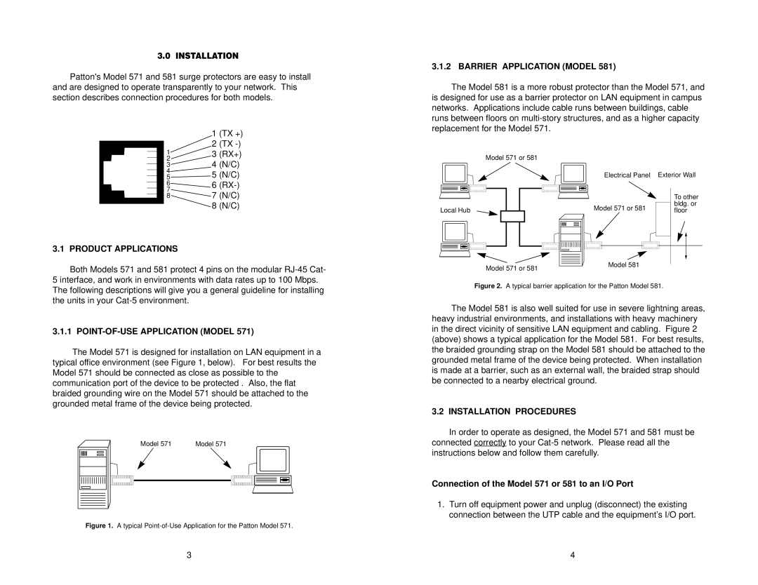
3.1.2 BARRIER APPLICATION (MODEL 581)
The Model 581 is a more robust protector than the Model 571, and is designed for use as a barrier protector on LAN equipment in campus networks. Applications include cable runs between buildings, cable runs between floors on
13 (RX+)
2
34 (N/C)
4
5 ![]() 5 (N/C)
5 (N/C)
6![]() 6
6
7
87 (N/C)
8 (N/C)
3.1PRODUCT APPLICATIONS
Both Models 571 and 581 protect 4 pins on the modular
Model 571 or 581
Local Hub
Model 571 or 581
Electrical Panel Exterior Wall
|
| To other |
Model 571 or 581 |
| bldg. or |
| ||
| floor | |
|
| |
|
|
|
Model 581
5 interface, and work in environments with data rates up to 100 Mbps. The following descriptions will give you a general guideline for installing the units in your
3.1.1 POINT-OF-USE APPLICATION (MODEL 571)
The Model 571 is designed for installation on LAN equipment in a typical office environment (see Figure 1, below). For best results the Model 571 should be connected as close as possible to the communication port of the device to be protected . Also, the flat braided grounding wire on the Model 571 should be attached to the grounded metal frame of the device being protected.
|
|
|
|
|
|
|
|
|
| Model 571 | Model 571 |
|
|
|
|
|
|
|
|
|
|
|
|
|
|
|
|
|
|
|
|
|
|
|
|
|
|
|
|
|
|
|
|
|
|
|
|
|
|
|
|
|
|
|
|
|
|
|
|
|
|
|
|
|
|
|
|
|
|
|
|
|
|
|
|
|
|
|
|
Figure 1. A typical Point-of-Use Application for the Patton Model 571.
Figure 2. A typical barrier application for the Patton Model 581.
The Model 581 is also well suited for use in severe lightning areas, heavy industrial environments, and installations with heavy machinery in the direct vicinity of sensitive LAN equipment and cabling. Figure 2 (above) shows a typical application for the Model 581. For best results, the braided grounding strap on the Model 581 should be attached to the grounded metal frame of the device being protected. When installation is made at a barrier, such as an external wall, the braided strap should be connected to a nearby electrical ground.
3.2 INSTALLATION PROCEDURES
In order to operate as designed, the Model 571 and 581 must be connected correctly to your
Connection of the Model 571 or 581 to an I/O Port
1.Turn off equipment power and unplug (disconnect) the existing connection between the UTP cable and the equipment’s I/O port.
3 | 4 |