APPENDIX A
MODEL 571/581 SPECIFICATIONS
Environment: | |
| connector, including |
| T, Token Ring, Fast Ethernet, |
| and ATM on a |
Connectors: | |
Response Time: | Clamped to 13 V after 0.1 µs |
Characteristic |
|
Impedance: | 100 Ohms |
NEXT Loss: | Model 571 - worst pair Better than |
| 100 MHz; Model 581 - worst pair Better |
| than |
Surge Clamp |
|
Voltage: | Model 571 - 13 V max with 1 KV Input; |
| Model 581 - 15 V max with 2 KV Input |
Surge Rating: | IEC 801.5 Standard Level |
DC Clamp Voltage: | Common Mode to Gnd, each line7.5 V @ 50 |
| mA; Differential mode, per pair 8.1 V @ 50 |
| mA |
Insertion Loss: | Less than 0.4 dB at 100 MHz (including |
| connector) |
Return Loss: | Better than 14 dB |
Group Delay: | None, 1 MHz to 100 MHz |
Series Resistance: | Less than 400 milliohms |
Grounding: | External ground strap provides separate |
| |
Dimensions: | 2.0L x 1.0”D |
APPENDIX B
MODEL 571/581 INTERNATIONAL ELECTROTECHNICAL
COMMISSION (IEC) COMPLIANCE
Meets IEC standards 801.2, 801.4 and 801.5 (CE Mark)
Effective January 1996 the European Economic Community will require that all electronic devices be tested and comply with all applicable International standards relating to the product type and category of use. Electromagnetic Compatibility Directive 89/336/EEC specifically addresses communication line surge protection devices, since conformity to immunity standard
*Note: All test results are for the Model 571/581 alone, not including the standard 6 inch (15.25) patch cable that is shipped with the unit.
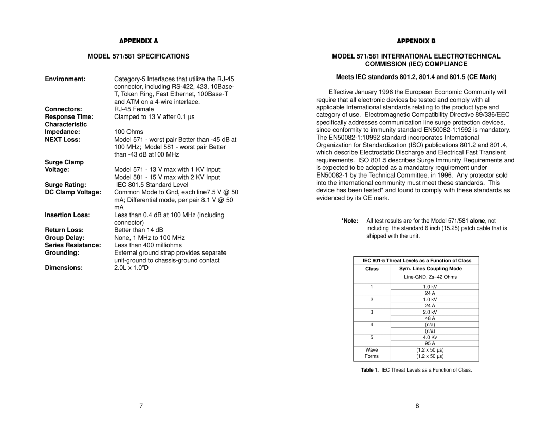
IEC
Class | Sym. Lines Coupling Mode | |
|
| |
|
|
|
1 |
| 1.0 kV |
|
| 24 A |
2 |
| 1.0 kV |
|
| 24 A |
3 |
| 2.0 kV |
|
| 48 A |
4 |
| (n/a) |
|
| (n/a) |
5 |
| 4.0 Kv |
|
| 95 A |
Wave | (1.2 x 50 µs) | |
Forms | (1.2 x 50 µs) | |
|
|
|
Table 1. IEC Threat Levels as a Function of Class.
7 | 8 |