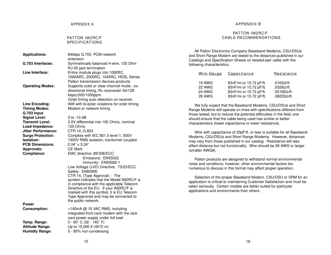
| APPENDIX A |
| PATTON IM2RC/F |
| SPECIFICATIONS |
Applications: | 64kbps G.703 PCM network |
| extension |
G.703 Interfaces: | Symmetrically balanced |
| |
Line Interface: | Entire module plugs into 1092RC, |
| 1092ARC, 2500RC, 1045RC, HDSL Series |
| Patton transmission devices products |
Operating Modes: | Supports octet or clear channel mode; co- |
| directional timing, Rx recovered: 64/128 |
| kbps±500/1000ppm. |
| Octet timing auto detection on receiver. |
Line Encoding: | AMI with |
Timing Modes: | Modem or network timing |
G.703 Input |
|
Signal Level: | 0 to |
Transmit Level: | 2.0V differential into 100 Ohms, nominal |
Load Impedance: | 120 Ohms |
Jitter Performance: | CTR 14, G.823 |
Surge Protection: | Complies with IEC 801.5 level 1, 500V |
Isolation: | 1500V RMS isolation, tranformer coupled |
PCB Dimensions: | 2.04” x 3.24” |
Approvals: | CE Mark |
Compliance: | EMC directive: 89/336/ECC |
| Emissions: EN55022 |
| Immunity: |
| Low Voltage (LVD) Directive: 73/23/ECC |
| Safety: EN60950 |
| CTR 14, (Type Approval) - The |
| symbol indicates that the Model IM2RC/F is |
| in compliance with the applicable Telecom |
| Directive of the EU. If your IM2RC/F is |
| marked with this symbol, it is EU Telecom |
| Type Approved and may be connected to |
Power | the public network. |
| |
Consumption: | <140mA @ 10 VAC RMS, including |
| integrated front card modem with the rack |
| card power supply under full load |
Temp. Range: | 0 - 60˚ C (32 - 140˚ F) |
Altitude Range: | Up to 15,000 ft (4572 m) |
Humidty Range: | 5 - 95% |
APPENDIX B
PATTON IM2RC/F
CABLE RECOMMENDATIONS
All Patton Electronics Company Baseband Modems, CSU/DSUs and Short Range Modem are tested to the distances published in our Catalogs and Specification Sheets on
Wire Gauge | Capacitance | Resistance |
19 AWG | 83nF/mi or 15.72 pF/ft. | .0163Ω/ft. |
22 AWG | 83nF/mi or 15.72 pF/ft. | .0326Ω/ft. |
24 AWG | 83nF/mi or 15.72 pF/ft. | .05165Ω/ft. |
26 AWG | 83nF/mi or 15.72 pF/ft. | .08235Ω/ft. |
We fully expect that the Baseband Modems, CSU/DSUs and Short Range Modems will operate on lines with specifications different from those tested, but to reduce the potential difficulties in the field, one should ensure that the cable being used has similar or better characteristics (lower capacitance or lower resistance).
Wire with capacitance of 20pF/ft. or less is suitable for all Baseband Modems, CSU/DSUs and Short Range Modems. However, distances may vary from those published in our catalog. Resistance will also affect distance but not functionality. Wire should be 26 AWG or larger (smaller AWG#).
Patton products are designed to withstand normal environmental noise and conditions; however, other environmental factors too numerous to discuss in this format may affect proper operation.
Selection of the proper Baseband Modem, CSU/DSU or SRM for an application is critical to maintaining Customer Satisfaction and must be taken seriously. Certain models are better suited for particular applications and environments than others.
15 | 16 |
