Patton electronic IM2RC/F Making Interface Connections, CONNECTING TO A G.703 PCM NETWORK CHANNEL

Models: IM2RC/F

1 11
Download 11 pages 22.23 Kb
Page 7
Image 7
4.3 MAKING INTERFACE CONNECTIONS

4.3 MAKING INTERFACE CONNECTIONS

The Model IM2RC/F is designed to provide access to a 64 kbps
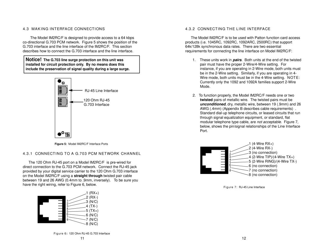
 co-directional G.703 PCM network. Figure 5 shows the position of the G.703 interface and the line interface of the IM2RC/F. This section describes how to connect the G.703 interface and the line interface.

RJ-45 Line Interface

120 Ohm RJ-45

G.703 Interface

Figure 5: Model IM2RC/F Interface Ports

4.3.1 CONNECTING TO A G.703 PCM NETWORK CHANNEL

The 120 Ohm RJ-45 port on a Model IM2RC/F is pre-wired for

direct connection to the G.703 PCM network. Connect the RJ-45 jack provided by your digital service carrier to the 120 Ohm G.703 interface on the Model IM2RC/F using a straight through twisted pair cable between 19 and 26 AWG (0.4mm to .9mm, inversely). To be sure you have the right wiring, refer to Figure 6, below.

1 (RX+)

2 (RX-)

3 (N/C)

4 (TX-)

5 (TX+)

6 (N/C)

7 (N/C)

8 (N/C)

Figure 6: 120 Ohm RJ-45 G.703 Interface

4.3.2 CONNECTING THE LINE INTERFACE

The Model IM2RC/F is to be used with Patton function card access products (i.e. 1045RC, 1092RC, 1092ARC, 2500RC) that support 64k/128k synchronous data rates. There are two essential requirements for connecting the line interface on Model IM2RC/F:

1.These units work in pairs. Both units at the end of the twisted pair must have the proper 2-Wire/4-Wire setting. For instance, if you are operating in 2-Wire mode, both units must be in the 2-Wire setting. Similarly, if you are operating in 4- Wire mode, both units must be in the 4-Wire setting. NOTE: Currently only the 1092 and 1092A families support 2-Wire Mode.

2.To function properly, the Model IM2RC/F needs one or two twisted pairs of metallic wire. The twisted pairs must be unconditioned, dry, metallic wire, between 19 (.9mm) and 26 AWG (.4mm) (Appendix B describes cable requirements) . Standard dial-up telephone circuits, or leased circuits that run through signal equalization equipment, or standard, flat modular telephone type cable, are not acceptable. Figure 7, below, shows the pin/signal relationships of the Line Interface Port.

1

2

3

44.3.1 CONNECTING TO A G.703 PCM NETWORK CHANNEL

54.3.2 CONNECTING THE LINE INTERFACE

6

7

8 Manual background

11

12

Page 7
Image 7
Patton electronic IM2RC/F user manual Making Interface Connections, CONNECTING TO A G.703 PCM NETWORK CHANNEL