Patton electronic IM2RC/I-100B Installation Model 1001R14 Rack Chassis, Rack Power Supply, Tion

Models: IM2RC/I-100B

1 20
Download 20 pages 26.15 Kb
Page 12
Image 12

5.0 INSTALLATION

This section describes the NetLink Model 1001R14 rack chassis. Included are installation instructions for the IM2RC/I-100B rear card, plus ethernet and line interface connections to the IM2RC/I-100B card. Please refer to the appropriate function card (i.e. 3088RC) user manual to configure and install the function card.

5.1 THE MODEL 1001R14 RACK CHASSIS

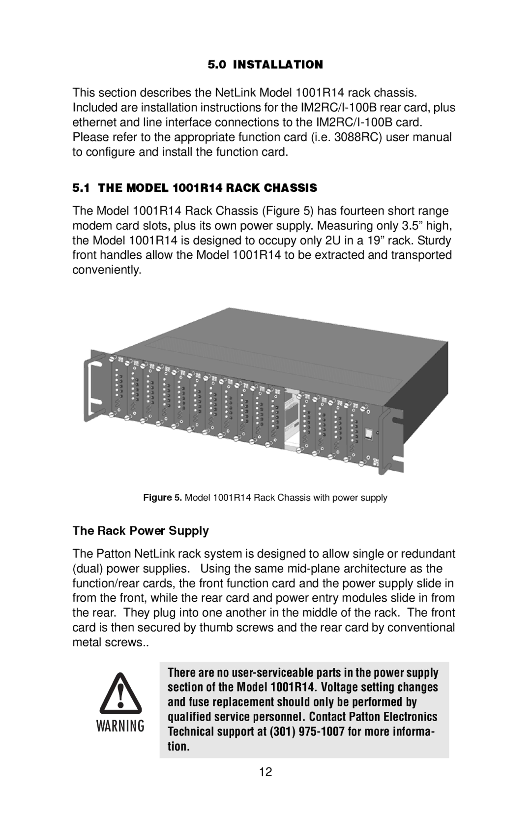
The Model 1001R14 Rack Chassis (Figure 5) has fourteen short range modem card slots, plus its own power supply. Measuring only 3.5” high, the Model 1001R14 is designed to occupy only 2U in a 19” rack. Sturdy front handles allow the Model 1001R14 to be extracted and transported conveniently.

Figure 5. Model 1001R14 Rack Chassis with power supply

The Rack Power Supply

The Patton NetLink rack system is designed to allow single or redundant (dual) power supplies. Using the same mid-plane architecture as the function/rear cards, the front function card and the power supply slide in from the front, while the rear card and power entry modules slide in from the rear. They plug into one another in the middle of the rack. The front card is then secured by thumb screws and the rear card by conventional metal screws..


There are no user-serviceable parts in the power supply


section of the Model 1001R14. Voltage setting changes


and fuse replacement should only be performed by

WARNING

qualified service personnel. Contact Patton Electronics

Technical support at (301) 975-1007 for more informa-


tion.

12

Page 12
Image 12
Patton electronic IM2RC/I-100B user manual Installation Model 1001R14 Rack Chassis, Rack Power Supply, Tion