SW2-4 and SW2-5: Clock Source
Switches
Setting | ||
On | On | Internal transmit clock |
Off | On | Receive recover clock |
On | Off | External transmit clock |
SW2-6: Carrier Control Method
The setting for switch
Setting | |
Off | Constantly on |
On | Controlled by RTS |
SW2-7 and SW2-8: RTS/CTS Delay
The combined settings for switches
Setting | ||
Off | Off | No delay |
On | On | 7ms |
On | Off | 53ms |
4.0 INSTALLATION
Once the Model 1035 is properly configured, it is ready to connect to your system. This section tells you how to properly connect the Model 1035 to the twisted pair,
4.1 CONNECTION TO THE TWISTED PAIR INTERFACE
The Model 1035 supports communication between two
1.These units work in pairs. Therefore, you must have one Model 1035 (or a compatible model) at each end of a two twisted pair interface.
2.To function properly, the Model 1035 needs two twisted pairs of metallic wire. These twisted pairs must be unconditioned, dry, metallic wire, between 19 and 26 AWG (the higher number gauges may limit distance somewhat). Standard
For your convenience, the Model 1035 is available with two different twisted pair interfaces:
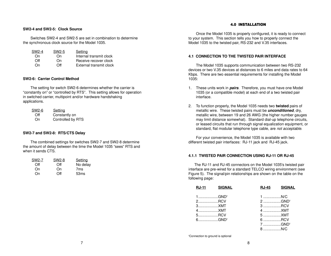
4.1.1 TWISTED PAIR CONNECTION USING RJ-11 OR RJ-45
The
SIGNAL | SIGNAL | ||
1 | GND† | 1 | N/C |
2 | RCV | 2 | GND† |
3 | XMT | 3 | RCV |
4 | XMT | 4 | XMT |
5 | RCV | 5 | XMT |
6 | GND† | 6 | RCV |
|
| 7 | GND† |
|
| 8 | N/C |
†Connection to ground is optional
7 | 8 |