When connecting two Model 1035s, it is necessary to use a twisted pair “crossover” cable. The diagram below shows how a crossover cable should be constructed for an environment where both Model 1035s use a
SIGNAL | PIN# | COLOR‡ | COLOR | PIN# | SIGNAL |
GND† | 1 | Blue | White | 6 | GND† |
RCV | 2 | Yellow | Red | 4 | XMT |
XMT | 3 | Green | Black | 5 | RCV |
XMT | 4 | Red | Yellow | 2 | RCV |
RCV | 5 | Black | Green | 3 | XMT |
GND† | 6 | White | Blue | 1 | GND† |
†Connection to ground is optional
‡Standard color
4.2 CONNECTION TO THE RS-232 AND V. 35 INTERFACES
Once you have connected the twisted pair wires correctly, simply plug the Model 1035 directly into the
4.2.1 CONNECTION TO A “DTE” DEVICE
The Model 1035 is wired as a DCE, and therefore “wants” to plug into a DTE such as a terminal, PC or host. A direct connection to the
|
|
|
|
| 1 | - Blue |
|
|
|
|
| ||
1 | - Blue |
|
|
| 2 | - Orange |
|
|
| ||||
2 | - Yellow |
|
|
| 3 | - Black |
|
|
| ||||
3 | - Green |
|
|
| 4 | - Red |
|
|
| ||||
4 | - Red |
|
|
| 5 | - Green |
|
|
| ||||
5 | - Black |
|
|
| 6 | - Yellow |
|
|
| ||||
6 | - White |
|
|
| 7 | - Brown |
|
|
| ||||
|
|
|
|
| 8 | - Slate |
|
|
|
|
| ||
|
|
|
|
|
|
|
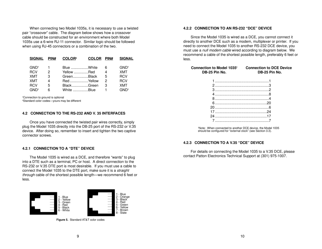
Figure 5. Standard AT&T color codes
4.2.2 CONNECTION TO AN RS-232 “DCE” DEVICE
Since the Model 1035 is wired as a DCE, you cannot connect it directly to another DCE such as a modem, multiplexer or printer. If you need to connect the Model 1035 to another
Connection to Model 1035† | Connection to DCE Device |
1 | 1 |
2 | 3 |
3 | 2 |
4 | 8 |
8 | 4 |
6 | 20 |
20 | 6 |
17 | 24 |
24 | 17 |
7 | 7 |
†Note: When connected to another DCE device, the Model 1035 should be configured for “external clock” (see Section 3.3).
4.2.3CONNECTION TO A V.35 “DCE” DEVICE
For details on connecting the Model 1035 to a V.35 DCE, please contact Patton Electronics Technical Support at (301)
9 | 10 |