Manuals
/
Peavey
/
Home Audio
/
Stereo Amplifier
Peavey
646-049
manual
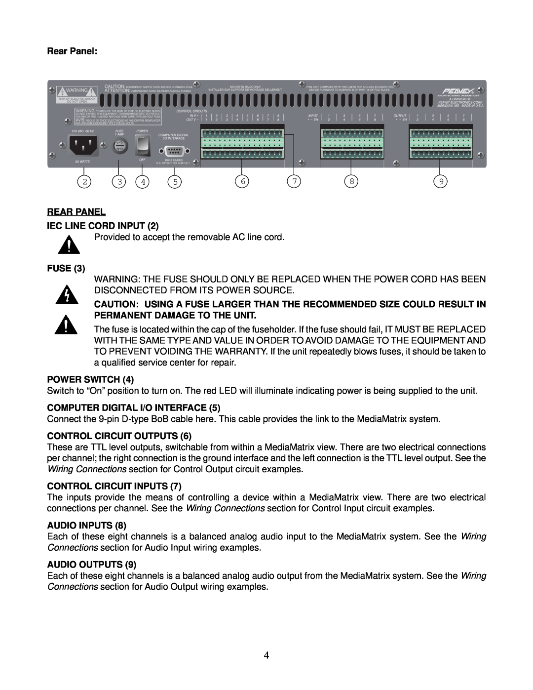
Rear Panel
Models:
646-049
1
4
20
20
Download
20 pages
32.84 Kb
1
2
3
4
5
6
7
8
Specs
Wiring Diagram
Warranty
Safety
IA 400 Power Amp
BoB Interface Features
Page 4
Image 4
Page 3
Page 5
Page 4
Image 4
Page 3
Page 5
Contents
MM MM MM
MM 8800 Series
O p e r a t i n g G u i d e
CAUTION Risk of electrical shock - DO NOT OPEN
BoB Interface Features
E N G L I S H
MediaMatrix
Rear Panel
SPECIFICATIONS
Wiring Diagram
Control Input Examples
Wiring Diagram
Control Output Examples
Wiring Diagram
1.Unbalanced audio device output to balanced BoB input
Wiring Diagram
IA 400 Power Amp
CD Player or Other Line Level Audio Device
MediaMatrix Computer
Wiring Diagram
IA 400 Power Amp
MediaMatrix System with Microphone Preamp
MediaMatrix Computer
E S P A Ñ O L
Consulte los diagramas del panel
Características de la interfaz “BoB”
delantero en la sección de inglés de este manual
Panel Trasero
Caractéristiques de l’interface « BoB »
F R A N Ç A I S
Veuillez-vousréférer au « front panel » art
Panneau Arrière
D E U T S C H
Merkmale der „BoB“-Schnittstelle
Rückplatte
Commercial Sound for Permanent Installations
Acoustics products, ask your Authorized Peavey
Sound Contractor for the appropriate
The BluePrint
LIMITED WARRANTY
IMPORTANT SAFETY INSTRUCTIONS
SAVE THESE INSTRUCTIONS
A Division of Peavey Electronics Corporation
#80300361
1996
ARCHITECTURAL ACOUSTICS
Top
Page
Image
Contents