Peavey CKV Series, CKS Series, CKX Series owner manual Rear Panel, Operation

Models: CKX Series CKS Series CKV Series

1 20
Download 20 pages 25.56 Kb
Page 6
Image 6

Rear Panel.

Module Bays & Modules.

The rear panel of CK Power Processing amplifiers provides three bays (Input, Network and Output/Power) configured to accept inter- changeable plug-in modules. Your amplifier may have been factory- configured with some of the optional modules. In this case, info on the relevant modules will be enclosed in the amplifier box, or in a separate binder. If all required information is not included, please call Crest Audio’s Customer Service department or your local Crest Audio representative.

About CC Modules and NC Modules.

CCmodules fit into the Power/Output or Input module bays in the rear panel of CK Power Processing amplifiers. These "basic" analog modules are non-programmable and non-NexSys®compatible; only the STO function can be controlled (through hardwiring).

NC Modules can be controlled, programmed and/or monitored. They fit into the rear panel of the amplifiers. NC Input Modules can be controlled and/or programmed over the NexSys network or via the N-Coder (Hand-Held) or N-Coder/PC software. (NexSys is Crest Audio’s hardware and software package that offers network connec- tion of Crest Audio amplifiers and associated devices.). NC Input and NC Output/Power Modules are NexSys-compatible. Using NexSys with the appropriate NC Network Module, NC Input and Output/Power Modules can be controlled, programmed and/or moni- tored remotely. NexSys also offers a number of diagnostic facilities. On the NC Input Modules, the individual channel attenuators offer manual level adjustment and removable knobs for additional securi- ty. Except for the STO feature, NC Modules are “tamper-proof” in that there are no user-accessible setup controls.

9. Circuit Breaker.

A re-settable, protective AC circuit breaker is located at the upper left of the amplifier rear panel. Two and three rack space amplifiers have a push-type breaker fitted, while four rack space units have a throw-switch style breaker. If the breaker has tripped, push it back in (or, in the case of four rack space units, flip the breaker up) to return the amplifier to operating condition. If the breaker trips repeatedly, the amplifier needs servicing.

10.IEC Power Connector with removable Power Cord or Captive Power Cord.

On two rack space amplifiers, a standard IEC power connector is located at the lower left corner of the amplifier rear panel. An AC mains cord having an appropriate AC plug for the intended operating voltage is included. Three and four rack space units have a captive power cord.

11.Power/Output Bay.

All Power/Output modules (CC-STL module is shipped standard) provide a ground lift jumper, barrier strip output connectors, and connections for sequential turn-on /off (STO) activation.

A barrier strip is provided for connection of loudspeakers with bare wire or spade lug connectors. A signal ground lift jumper permits the audio ground to be lifted from the chassis ground. For more informa- tion see the sections on Signal Ground Lift Jumper, Module Removal, and Sequential Turn-On/Turn-Off.

12. Network Bay.

The CC-BLK (blank panel) comes standard with all amplifiers. See the section on Replacing or Installing a Network Module for more information.

13. Input Bay.

CK Power Processing amplifiers come standard with a CC-IPB Input module. Barrier strip input connectors and individual channel rotary attenuators are provided. All Input modules have an internal voltage gain/input sensitivity jumper that is factory-set for X40 gain. See the sections on Input module Connections and Removing or Replacing an Input module for more information.

Operation.

Connecting Power/Circuit Size Requirements.

CK Power Processing amplifier power requirements are rated at “idle”, 1/8th power (“typical” music conditions), 1/3rd power, and maximum rated power. The maximum power current draw rating is limited by the amplifier's circuit breaker. Consult the specifications at the end of this manual for the current that each amplifier will demand. AC mains voltage must be the same as that indicated on the rear of the amplifier. Damage caused by connecting the amplifier to improper AC voltage is not covered by any warranty. Note: Always turn off and disconnect the amplifier from the mains voltage before making audio connections. If possible, as an extra precaution, have the attenuators turned down during power-up.

Cooling Requirements.

CK Power Processing amplifiers use a
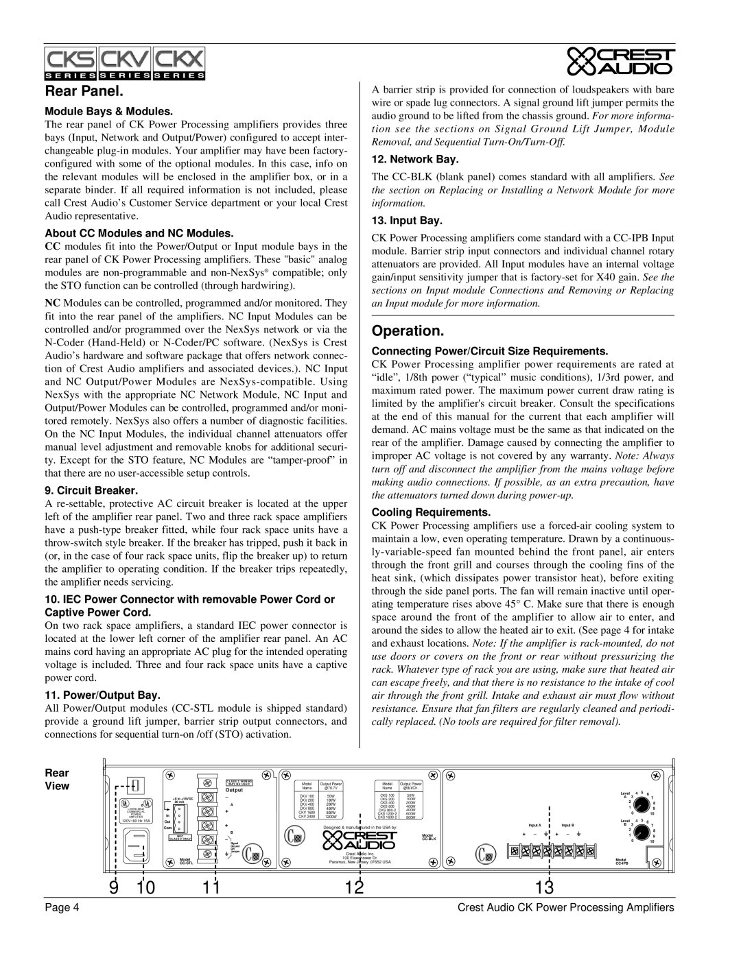
 forced-air cooling system to maintain a low, even operating temperature. Drawn by a continuous- ly-variable-speed fan mounted behind the front panel, air enters through the front grill and courses through the cooling fins of the heat sink, (which dissipates power transistor heat), before exiting through the side panel ports. The fan will remain inactive until oper- ating temperature rises above 45° C. Make sure that there is enough space around the front of the amplifier to allow air to enter, and around the sides to allow the heated air to exit. (See page 4 for intake and exhaust locations. Note: If the amplifier is rack-mounted, do not use doors or covers on the front or rear without pressurizing the rack. Whatever type of rack you are using, make sure that heated air can escape freely, and that there is no resistance to the intake of cool air through the front grill. Intake and exhaust air must flow without resistance. Ensure that fan filters are regularly cleaned and periodi- cally replaced. (No tools are required for filter removal).

Rear View

+8 to +18VDC

20 mA

LISTED 8B42

COMMERCIAL

POWER

AMPLIFIERIn

120V~60 Hz 15A

Out

Com

NEC

CLASS 2 ONLY

Model

CC-STL

CLASS 2 WIRING MAY BE USED

Output

A

+

+

B

Signal

Ground

Lift

Jumper

Model

Output Power

Model

Output Power

Name

@70.7V

Name

@8Ω/Ch.

CKV 100

50W

CKS 100

50W

CKV 200

100W

CKS 200

100W

CKV 400

200W

CKS 400

200W

CKS 800

400W

CKV 800

400W

CKS 800-2

400W

CKV 1600

800W

CKS 1200-2

600W

CKV 2400

1200W

CKS 1600-2

800W

Designed & manufactured in the USA by:

Model

CC-BLK

Crest Audio Inc.

100 Eisenhower Dr.

Paramus, New Jersey 07652 USA


Level

3

4

5

6


A


7


2


8


1


9


0


10


Level

3

4

5

6


Input A


Input B


B


7

+


+


2


8


1


9


0


10


Model

CC-IPB

9

10

11

12

13

Page 4

Crest Audio CK Power Processing Amplifiers

Page 6
Image 6
Peavey CKV Series, CKS Series, CKX Series owner manual Rear Panel, Operation