Input Bay.
Input Module Connections and Controls.
Input barrier strips have a 0.325" (8.3mm) center and 0.270" (6.9mm) lug space. For connecting to the input barrier strips, a wire gauge between 14 AWG (2.5mm2) & 24 AWG (0.25mm2), and spade lugs (Panduit Part No. PNF
Input Module Connections and Controls Diagram. | |||||||
SEE INSTRUCTION MANUAL |
|
|
|
| |||
|
|
|
| Level | 4 | 5 | 6 |
|
|
|
| A | 3 |
| 7 |
|
|
|
|
| 2 |
| 8 |
|
|
|
|
| 1 |
| 9 |
|
|
|
|
|
|
| |
|
|
|
|
| 0 |
| 10 |
|
|
|
| Level | 4 | 5 | 6 |
| Input A |
| Input B | B | 3 |
| 7 |
+ | – | + | – |
| 2 |
| 8 |
| 1 |
| 9 | ||||
|
|
|
|
|
|
| |
|
|
|
|
| 0 |
| 10 |
|
|
|
| Model |
|
|
|
|
|
|
|
|
|
| |
Input Barrier Strip |
| Input Level | |||||
| Attenuators | ||||||
Removable Attenuator Knobs.
The attenuator knobs can be removed and replaced with blanking plugs. These plugs are shipped with the amplifier. The procedure for attenuator knob removal is as follows:
1.With an
2.Using a needle nose pliers or appropriate size nut driver, loosen the inside nut.
3.Slide the attenuator knob off the shaft.
4.Insert a regular screwdriver in the slotted end of the shaft, and adjust attenuation to desired level.
5.Blanking plugs may now be inserted in the attenuator holes.
Unbalanced Sources.
For use with an unbalanced source, tie the inverting (minus) input to ground by installing a jumper across the appropriate barrier strip ter- minals. If the inverting input is left floating, a 6 dB loss in gain will result. See the diagram below.
Input Balanced /Unbalanced Connections Diagram. | |||||||
SEE INSTRUCTION MANUAL |
|
|
|
| |||
|
|
|
| Level | 4 | 5 | 6 |
|
|
|
| A | 3 |
| 7 |
|
|
|
|
| 2 |
| 8 |
|
|
|
|
| 1 |
| 9 |
|
|
|
|
| 0 |
| 10 |
|
|
|
| Level | 4 | 5 | 6 |
| Input A |
| Input B | B | 3 |
| 7 |
+ | – | + | – |
| 2 |
| 8 |
| 1 |
| |||||
|
| 9 | |||||
|
|
|
|
| 0 |
| 10 |
|
|
|
| Model |
|
|
|
|
|
|
|
|
|
| |
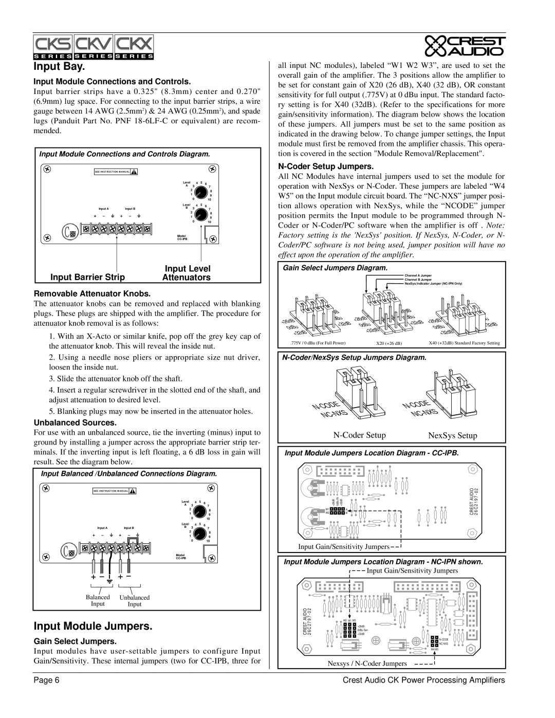
all input NC modules), labeled “W1 W2 W3”, are used to set the overall gain of the amplifier. The 3 positions allow the amplifier to be set for constant gain of X20 (26 dB), X40 (32 dB), OR constant sensitivity for full output (.775V) at 0 dBu input. The standard facto- ry setting is for X40 (32dB). (Refer to the specifications for more gain/sensitivity information). The diagram below shows the location of these jumpers. All jumpers must be set to the same position as indicated in the drawing below. To change jumper settings, the Input module must first be removed from the amplifier chassis. This opera- tion is covered in the section "Module Removal/Replacement".
N-Coder Setup Jumpers.
All NC Modules have internal jumpers used to set the module for operation with NexSys or
Gain Select Jumpers Diagram. |
|
|
| |||
|
|
| Channel A Jumper |
| ||
|
|
| Channel B Jumper |
| ||
|
|
| NexSys Indicator Jumper |
| ||
|
| +26dB |
|
| ||
| 0dBu | +26dB | 0dBu | +26dB |
| |
+26dB | +32dB |
| ||||
+32dB | 0dBu | +32dB | ||||
| 0dBu | |||||
0dBu |
| |||||
| +32dB |
|
| |||
+32dB |
|
| +32dB |
| ||
|
|
|
| |||
.775V / 0 dBu (For Full Power) | X20 (+26 dB) |
| X40 (+32dB) Standard Factory Setting | |||
CODE | CODE |
| |
N- |
| ||
N- |
|
| |
|
| ||
| NC |
| |
NC |
|
| |
|
| NexSys Setup | |
Input Module Jumpers Location Diagram - |
| ||
W1 | A | CRESTAUDIO | |
W2 | +26dB 0dBuIN +32dB B | ||
Input Gain/Sensitivity Jumpers |
|
| |
Input Module Jumpers Location Diagram -
+ – | + – |
Balanced | Unbalanced |
Input | Input |
Input Module Jumpers.
Gain Select Jumpers.
Input modules have
CREST AUDIO 2 6 C 2 7 9 7 - 0 2
W2 W1 W3
Input Gain/Sensitivity Jumpers
+26dB 0dBu Sen +32dB
![]()
![]()
![]()
![]()
W4 W5
Nexsys /
Page 6 | Crest Audio CK Power Processing Amplifiers |