PANEL DESCRIPTION
(1) FUSE
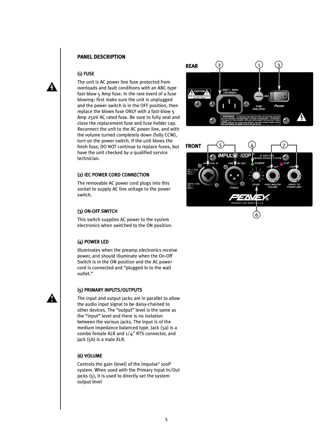
The unit is AC power line fuse protected from overloads and fault conditions with an ABC-type fast-blow 5 Amp fuse. In the rare event of a fuse blowing: first make sure the unit is unplugged and the power switch is in the OFF position, then replace the blown fuse ONLY with a fast-blow 5 Amp 250V AC rated fuse. Be sure to fully seat and close the replacement fuse and fuse holder cap. Reconnect the unit to the AC power line, and with the volume turned completely down (fully CCW), turn on the power switch. If the unit blows the fresh fuse, DO NOT continue to replace fuses, but have the unit checked by a qualified service technician.
(2) IEC POWER CORD CONNECTION
The removable AC power cord plugs into this socket to supply AC line voltage to the power switch.
(3) ON-OFF SWITCH
This switch supplies AC power to the system electronics when switched to the ON position.
(4) POWER LED
Illuminates when the preamp electronics receive power, and should illuminate when the On-Off Switch is in the ON position and the AC power cord is connected and “plugged in to the wall outlet.”
(5) PRIMARY INPUTS/OUTPUTS
The input and output jacks are in parallel to allow the audio input signal to be daisy-chained to other devices. The “output” level is the same as the “input” level and there is no isolation between the various jacks. The input is of the medium impedance balanced type. Jack (5a) is a combo female XLR and 1/4" RTS connector, and jack (5b) is a male XLR.
(6) VOLUME
Controls the gain (level) of the Impulse® 100P system. When used with the Primary Input In/Out jacks (5), it is used to directly set the system output level