S T E R E O M O D E O P E R AT I O N
F R O N T PA N E L
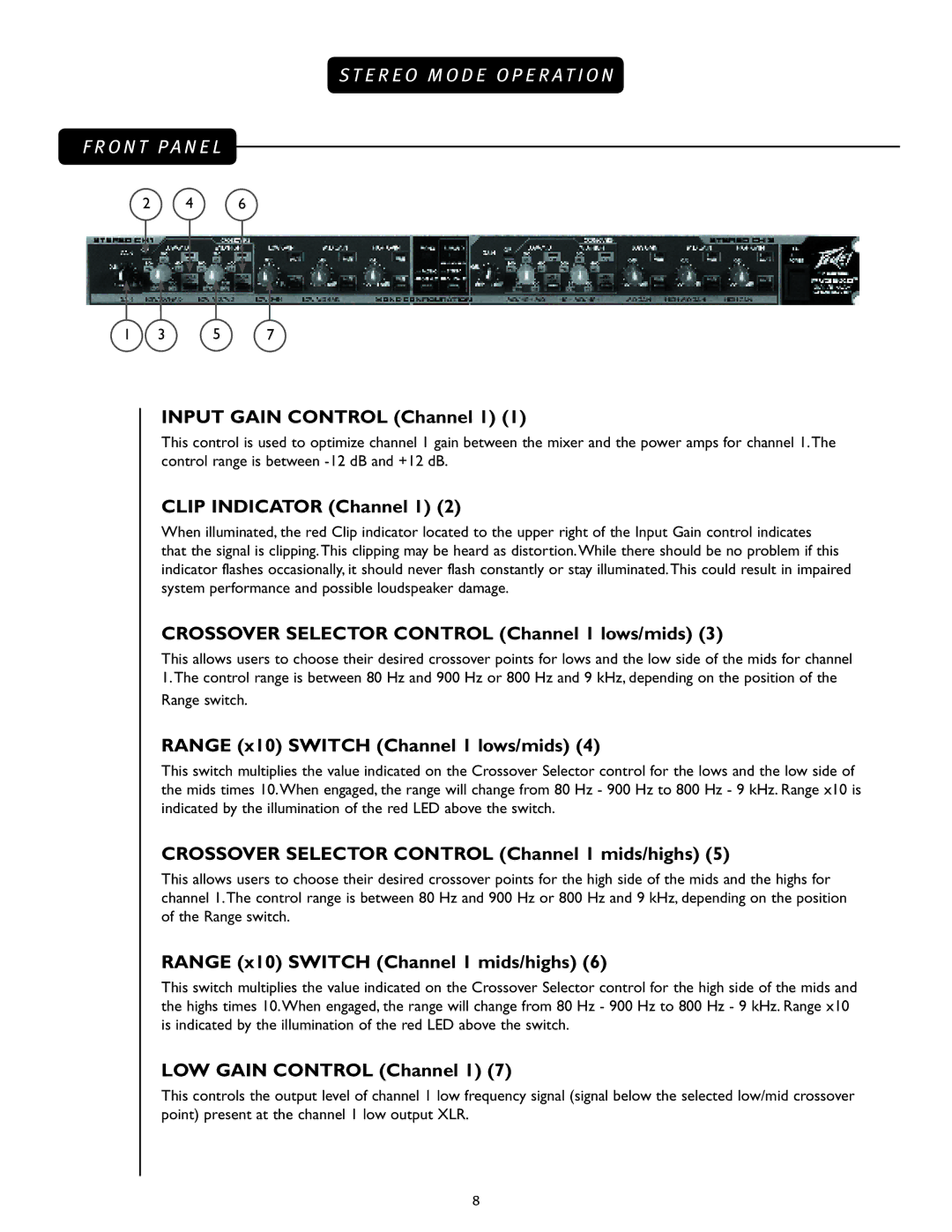
2 4 6
1 | 3 | 5 | 7 |
INPUT GAIN CONTROL (Channel 1) (1)
This control is used to optimize channel 1 gain between the mixer and the power amps for channel 1.The control range is between
CLIP INDICATOR (Channel 1) (2)
When illuminated, the red Clip indicator located to the upper right of the Input Gain control indicates that the signal is clipping.This clipping may be heard as distortion.While there should be no problem if this indicator flashes occasionally, it should never flash constantly or stay illuminated.This could result in impaired system performance and possible loudspeaker damage.
CROSSOVER SELECTOR CONTROL (Channel 1 lows/mids) (3)
This allows users to choose their desired crossover points for lows and the low side of the mids for channel
1.The control range is between 80 Hz and 900 Hz or 800 Hz and 9 kHz, depending on the position of the Range switch.
RANGE (x10) SWITCH (Channel 1 lows/mids) (4)
This switch multiplies the value indicated on the Crossover Selector control for the lows and the low side of the mids times 10.When engaged, the range will change from 80 Hz - 900 Hz to 800 Hz - 9 kHz. Range x10 is indicated by the illumination of the red LED above the switch.
CROSSOVER SELECTOR CONTROL (Channel 1 mids/highs) (5)
This allows users to choose their desired crossover points for the high side of the mids and the highs for channel 1.The control range is between 80 Hz and 900 Hz or 800 Hz and 9 kHz, depending on the position of the Range switch.
RANGE (x10) SWITCH (Channel 1 mids/highs) (6)
This switch multiplies the value indicated on the Crossover Selector control for the high side of the mids and the highs times 10.When engaged, the range will change from 80 Hz - 900 Hz to 800 Hz - 9 kHz. Range x10 is indicated by the illumination of the red LED above the switch.
LOW GAIN CONTROL (Channel 1) (7)
This controls the output level of channel 1 low frequency signal (signal below the selected low/mid crossover point) present at the channel 1 low output XLR.
8