Master Bus Output and Link Connections
These connections allow you to expand your SMR™821a. The Bus Links connector has 5 pins for combining multiple units. Using a
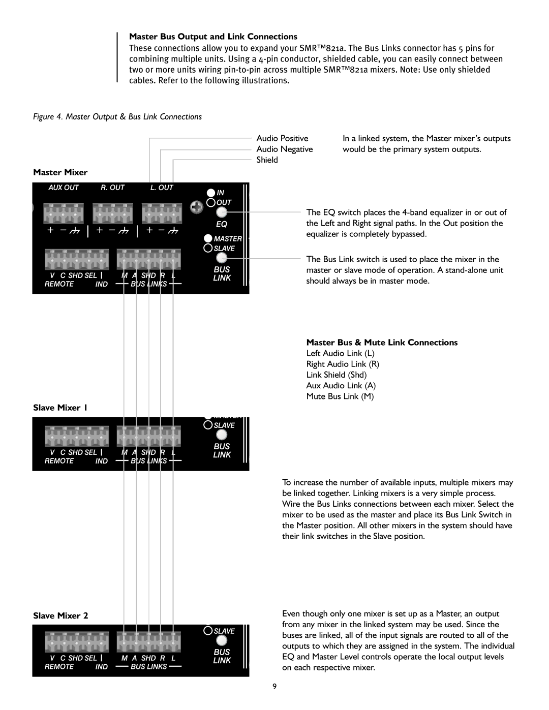
Figure 4. Master Output & Bus Link Connections
Master Mixer
Slave Mixer 1
Slave Mixer 2
Audio Positive | In a linked system‚ the Master mixer’s outputs |
Audio Negative | would be the primary system outputs. |
Shield |
|
The EQ switch places the
The Bus Link switch is used to place the mixer in the master or slave mode of operation. A
Master Bus & Mute Link Connections
Left Audio Link (L)
Right Audio Link (R)
Link Shield (Shd)
Aux Audio Link (A)
Mute Bus Link (M)
To increase the number of available inputs‚ multiple mixers may be linked together. Linking mixers is a very simple process. Wire the Bus Links connections between each mixer. Select the mixer to be used as the master and place its Bus Link Switch in the Master position. All other mixers in the system should have their link switches in the Slave position.
Even though only one mixer is set up as a Master‚ an output from any mixer in the linked system may be used. Since the buses are linked‚ all of the input signals are routed to all of the outputs to which they are assigned in the system. The individual EQ and Master Level controls operate the local output levels on each respective mixer.
9