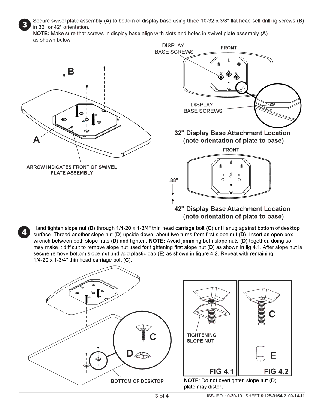
3 | Secure swivel plate assembly (A) to bottom of display base using three |
in 32" or 42" orientation. | |
| NOTE: Make sure that screws in display base align with slots and holes in swivel plate assembly (A) |
| as shown below. |
DISPLAY | FRONT | |
BASE SCREWS | ||
|
B
A
ARROW INDICATES FRONT OF SWIVEL
PLATE ASSEMBLY
DISPLAY
BASE SCREWS
32" Display Base Attachment Location (note orientation of plate to base)
FRONT
.88"
| 42" Display Base Attachment Location |
| (note orientation of plate to base) |
4 | Hand tighten slope nut (D) through |
surface. Thread another slope nut (D) |
wrench between both slope nuts (D) and tighten. NOTE: Avoid jamming both slope nuts (D) together, doing so may make it difficult to remove slope nut used for tightening first slope nut (D) as shown in fig 4.1. After slope nut is secure remove bottom slope nut and add plastic cap (E) as shown in figure 4.2. Repeat with remaining
![]() C
C
D ![]()
![]() C
C
Detail 1
BOTTOM OF DESKTOP
C
TIGHTENING
SLOPE NUT
E
FIG 4.1 | FIG 4.2 |
NOTE: Do not overtighten slope nut (D) plate may distort
3 of 4 | ISSUED: |