OPTIONAL
NOTE: Adjustment points (socket screws) are factory torqued for optimal performance. This factory torque setting is recommended to prevent the screen from slipping over time. If more or less tension is desired follow this optional step. You may not achieve optimal torque value if factory torque settings are adjusted.
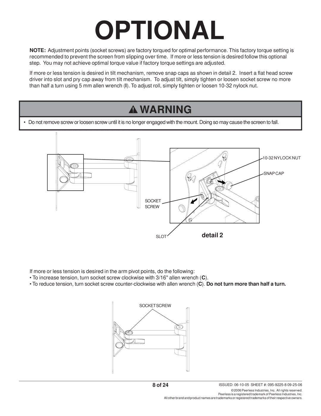
If more or less tension is desired in tilt mechanism, remove snap caps as shown in detail 2. Insert a flat head screw driver into slot and pry cap away from tilt mechanism. To adjust tilt, simply tighten or loosen socket screw no more than half a turn using 5 mm allen wrench (I). To adjust roll, simply tighten or loosen
![]() WARNING
WARNING
• Do not remove screw or loosen screw until it is no longer engaged with the mount. Doing so may cause the screen to fall.
| |
| SNAP CAP |
SOCKET |
|
SCREW |
|
SLOT | detail 2 |
If more or less tension is desired in the arm pivot points, do the following:
•To increase tension, turn socket screw clockwise with 3/16" allen wrench (C).
•To reduce tension, turn socket screw
SOCKETSCREW
8 of 24 | ISSUED: |
© 2006 Peerless Industries, Inc. All rights reserved. Peerless is a registered trademark of Peerless Industries, Inc.
All other brand and product names are trademarks or registered trademarks of their respective owners.