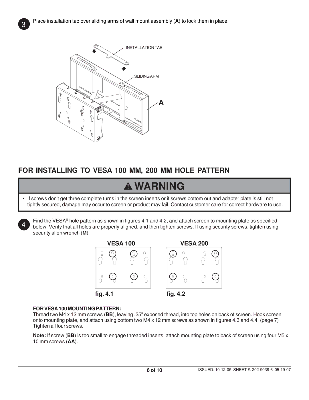
3 Place installation tab over sliding arms of wall mount assembly (A) to lock them in place.
INSTALLATION TAB
SLIDINGARM
A
FOR INSTALLING TO VESA 100 MM, 200 MM HOLE PATTERN
![]() WARNING
WARNING
•If screws don't get three complete turns in the screen inserts or if screws bottom out and adapter plate is still not tightly secured, damage may occur to screen or product may fail. Contact customer care for correct hardware to use.
4 | Find the VESA® hole pattern as shown in figures 4.1 and 4.2, and attach screen to mounting plate as specified | |
below. Verify that all holes are properly aligned, and then tighten screws. If using security screws, tighten using | ||
| security allen wrench (M). |
|
| VESA 100 | VESA 200 |
fig. 4.1 | fig. 4.2 |
FOR VESA 100 MOUNTING PATTERN:
Thread two M4 x 12 mm screws (BB), leaving .25" exposed thread, into top holes on back of screen. Hook screen onto mounting plate, and attach using bottom two M4 x 12 mm screws as shown in figures 4.3 and 4.4. (page 7) Tighten all four screws.
Note: If screw (BB) is too small to engage threaded inserts, attach mounting plate to back of screen using four M5 x 10 mm screws (AA).
6 of 10 | ISSUED: |