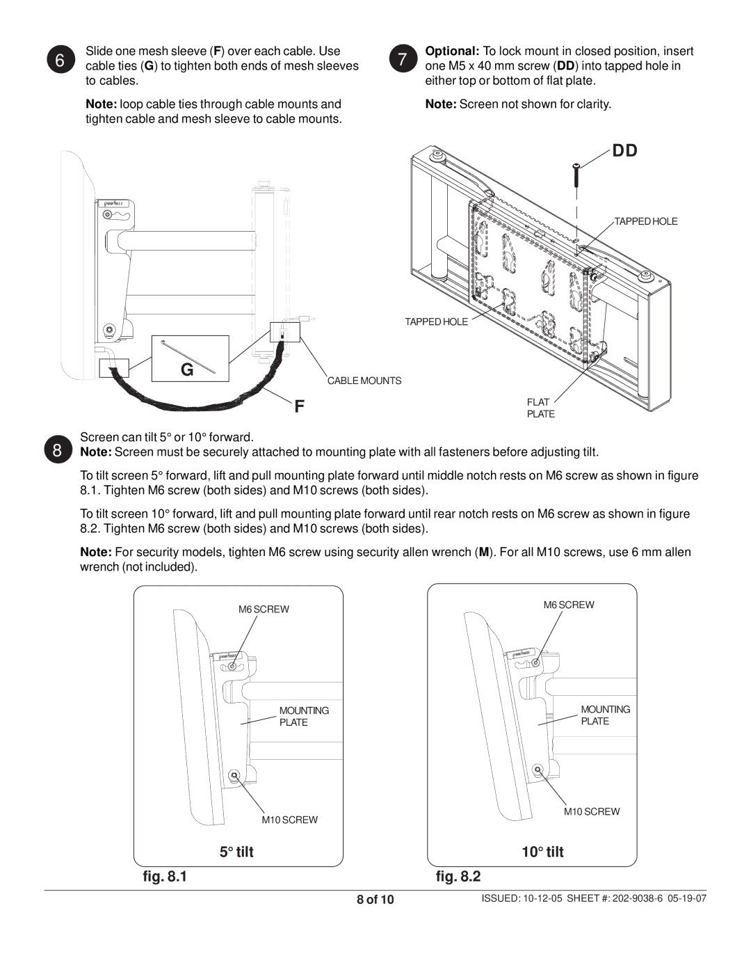
6 | Slide one mesh sleeve (F) over each cable. Use |
cable ties (G) to tighten both ends of mesh sleeves |
to cables.
Note: loop cable ties through cable mounts and tighten cable and mesh sleeve to cable mounts.
7 | Optional: To lock mount in closed position, insert |
one M5 x 40 mm screw (DD) into tapped hole in |
either top or bottom of flat plate.
Note: Screen not shown for clarity.
G
DD
TAPPED HOLE
TAPPED HOLE
F | CABLE MOUNTS |
| FLAT |
| |||
|
| ||
|
| PLATE |
Screen can tilt 5° or 10° forward.
8 Note: Screen must be securely attached to mounting plate with all fasteners before adjusting tilt.
To tilt screen 5° forward, lift and pull mounting plate forward until middle notch rests on M6 screw as shown in figure 8.1. Tighten M6 screw (both sides) and M10 screws (both sides).
To tilt screen 10° forward, lift and pull mounting plate forward until rear notch rests on M6 screw as shown in figure 8.2. Tighten M6 screw (both sides) and M10 screws (both sides).
Note: For security models, tighten M6 screw using security allen wrench (M). For all M10 screws, use 6 mm allen wrench (not included).
M6 SCREW | M6 SCREW |
|
MOUNTING | MOUNTING |
PLATE | PLATE |
| M10 SCREW |
| M10 SCREW |
5° tilt | 10° tilt |
fig. 8.1 | fig. 8.2 |
8 of 10 | ISSUED: |