Installation to Wood Stud Wall
![]() WARNING
WARNING
•Installer must verify that the supporting surface will safely support the combined load of the equipment and all attached hardware and components.
•Tighten wood screws so that wall plate is firmly attached, but do not overtighten. Overtightening can damage the screws, greatly reducing their holding power.
•Never tighten in excess of 80 in. • lb (9 N.M.).
•Make sure that mounting screws are anchored into the center of the stud. The use of an "edge to edge" stud finder is highly recommended.
•Hardware provided is for attachment of mount through standard thickness drywall or plaster into wood studs. Install- ers are responsible to provide hardware for other types of mounting situations.
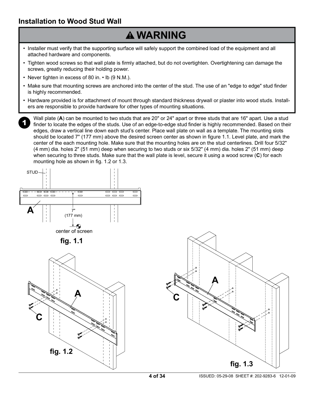
Wall plate (A) can be mounted to two studs that are 20" or 24" apart or three studs that are 16" apart. Use a stud
1finder to locate the edges of the studs. Use of an
STUD ![]()
|
|
|
|
|
|
|
|
|
|
|
|
|
|
|
|
|
|
|
|
|
|
|
|
|
|
|
|
|
|
|
|
|
|
|
|
|
|
|
|
|
|
|
|
|
|
|
|
|
|
|
|
|
|
|
|
|
|
|
|
|
|
|
|
|
|
|
|
|
|
|
|
|
|
|
|
|
|
|
|
|
|
|
|
|
|
|
|
|
|
|
|
|
|
|
|
|
|
|
|
|
|
|
|
|
| A |
|
|
|
|
|
|
|
|
|
|
|
|
|
|
|
|
|
|
|
| |||
|
|
|
| 7" |
|
|
|
|
|
|
|
|
|
|
| ||||||||||
|
|
|
|
|
|
|
|
|
|
|
|
|
| mm) |
|
| |||||||||
|
|
|
|
|
|
|
|
|
|
| (177 | ||||||||||||||
|
|
|
|
|
|
|
|
|
|
|
|
|
|
|
|
|
|
|
|
|
|
|
|
|
|
|
|
|
|
|
|
|
|
|
|
|
|
|
|
|
|
|
|
|
|
|
|
|
|
|
|
|
|
|
|
|
|
|
|
|
|
|
|
|
|
|
|
|
|
|
|
|
|
|
|
|
|
center of screen
fig. 1.1
A
C
fig. 1.2
C
A
fig. 1.3
4 of 34 | ISSUED: |