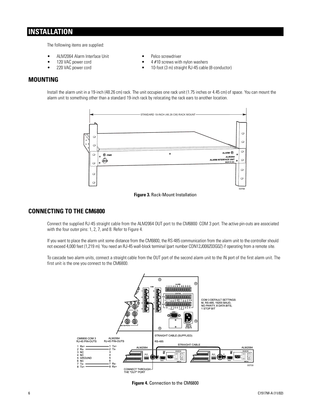
ALM2064 specifications
The Pelco ALM2064 is a state-of-the-art surveillance system designed to enhance security and monitoring capabilities in various environments. This advanced video surveillance solution is a part of Pelco's extensive range of high-performance cameras and accessories, catering to multiple industries, including retail, transportation, and critical infrastructure.One of the standout features of the ALM2064 is its exceptional image quality. Equipped with a high-resolution sensor, the camera provides sharp and clear images, ensuring that even the finest details are captured effectively. With the ability to deliver high-definition video up to 1080p, users can confidently monitor areas of interest without compromising on clarity.
The ALM2064 incorporates advanced technologies such as Wide Dynamic Range (WDR) and digital noise reduction, which significantly improve image quality in challenging lighting conditions. WDR allows the camera to simultaneously capture details in both bright and dark areas of the scene, making it ideal for environments with varying light sources. Digital noise reduction minimizes graininess in low-light situations, ensuring that surveillance footage remains clear and usable.
Another crucial characteristic of the ALM2064 is its versatility in deployment. The camera supports various mounting options, including wall, ceiling, and pole mounts, allowing for flexible installation in different settings. This adaptability makes it suitable for indoor and outdoor applications, as it can easily be integrated into existing security systems.
The ALM2064 is also designed with durability in mind. Its robust housing offers protection against harsh weather conditions, making it suitable for outdoor use. With an IP66 rating, it is resistant to dust and water, ensuring reliable performance in challenging environments.
In terms of connectivity, the Pelco ALM2064 supports various protocols for seamless integration with different Video Management Systems (VMS). This compatibility enhances its usability, allowing users to centralize their surveillance operations and manage multiple camera feeds efficiently.
User-friendliness is another notable aspect of the ALM2064. The camera features an intuitive interface that simplifies setup and configuration, ensuring that users can quickly get their systems up and running. Coupled with remote access capabilities, users can monitor live feeds and recorded footage from anywhere, providing flexibility and peace of mind.
In summary, the Pelco ALM2064 represents a cutting-edge solution for video surveillance, combining advanced image quality, durability, and versatile deployment options. Whether for commercial, industrial, or public safety applications, this camera meets the demands of modern security needs with reliability and performance.

