CABLE CONNECTIONS AND REQUIREMENTS
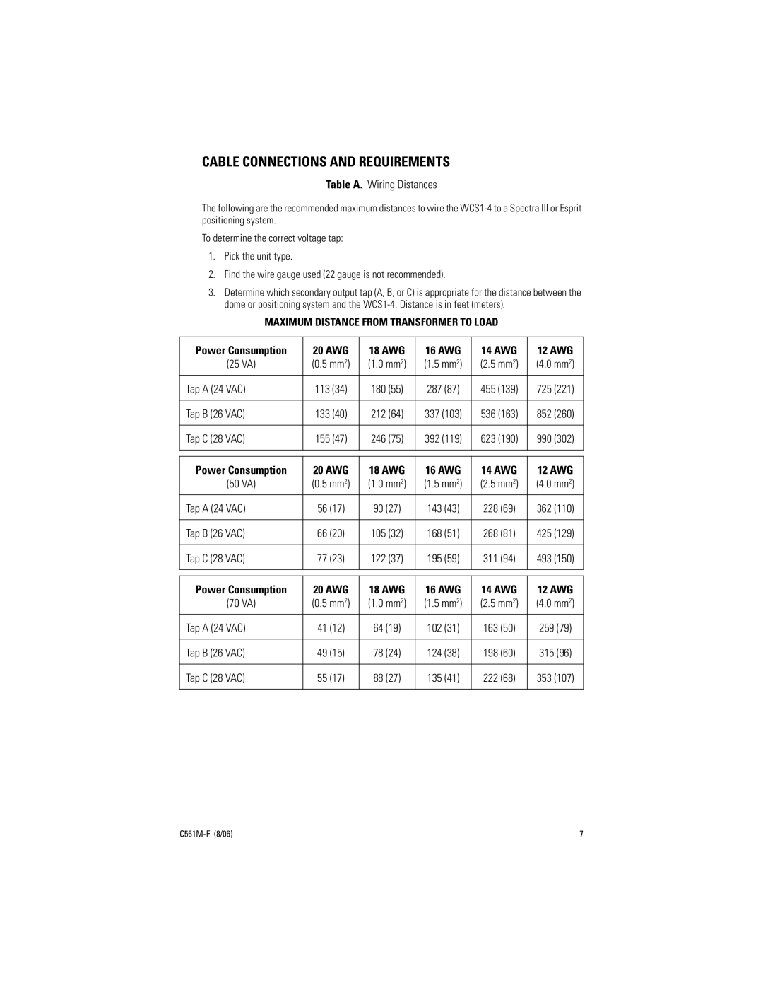
Table A. Wiring Distances
The following are the recommended maximum distances to wire the
To determine the correct voltage tap:
1.Pick the unit type.
2.Find the wire gauge used (22 gauge is not recommended).
3.Determine which secondary output tap (A, B, or C) is appropriate for the distance between the dome or positioning system and the
MAXIMUM DISTANCE FROM TRANSFORMER TO LOAD
Power Consumption | 20 AWG | 18 AWG | 16 AWG | 14 AWG | 12 AWG |
(25 VA) | (0.5 mm2) | (1.0 mm2) | (1.5 mm2) | (2.5 mm2) | (4.0 mm2) |
|
|
|
|
|
|
Tap A (24 VAC) | 113 (34) | 180 (55) | 287 (87) | 455 (139) | 725 (221) |
|
|
|
|
|
|
Tap B (26 VAC) | 133 (40) | 212 (64) | 337 (103) | 536 (163) | 852 (260) |
|
|
|
|
|
|
Tap C (28 VAC) | 155 (47) | 246 (75) | 392 (119) | 623 (190) | 990 (302) |
|
|
|
|
|
|
Power Consumption | 20 AWG | 18 AWG | 16 AWG | 14 AWG | 12 AWG |
(50 VA) | (0.5 mm2) | (1.0 mm2) | (1.5 mm2) | (2.5 mm2) | (4.0 mm2) |
|
|
|
|
|
|
Tap A (24 VAC) | 56 (17) | 90 (27) | 143 (43) | 228 (69) | 362 (110) |
|
|
|
|
|
|
Tap B (26 VAC) | 66 (20) | 105 (32) | 168 (51) | 268 (81) | 425 (129) |
|
|
|
|
|
|
Tap C (28 VAC) | 77 (23) | 122 (37) | 195 (59) | 311 (94) | 493 (150) |
|
|
|
|
|
|
Power Consumption | 20 AWG | 18 AWG | 16 AWG | 14 AWG | 12 AWG |
(70 VA) | (0.5 mm2) | (1.0 mm2) | (1.5 mm2) | (2.5 mm2) | (4.0 mm2) |
|
|
|
|
|
|
Tap A (24 VAC) | 41 (12) | 64 (19) | 102 (31) | 163 (50) | 259 (79) |
|
|
|
|
|
|
Tap B (26 VAC) | 49 (15) | 78 (24) | 124 (38) | 198 (60) | 315 (96) |
|
|
|
|
|
|
Tap C (28 VAC) | 55 (17) | 88 (27) | 135 (41) | 222 (68) | 353 (107) |
|
|
|
|
|
|
7 |
