BACK PANEL LAYOUT
1
CAM1 | CAM2 | CAM3 | CAM4 | CAM5 | CAM6 |
|
CAM7 | CAM8 | CAM9 | CAM10 | CAM11 | CAM12 |
|
CAM13 | CAM14 | CAM15 |
| 3 |
|
|
CAM16 | VIDEO |
| 5 | |||
SENSOR |
|
| RELAY | OUTPUT |
| |
1 2 3 4 | 5 6 7 8 | COM | 1 2 3 | 4 5 6 7 | 8 COM | |
| 2 |
| 4 |
| ||
| 18 | 16 |
| 1 12 2 |
| 8 | |
19 | 17 |
| Audio | ||||
15 | 1 | MIC | |||||
2 | 13 | 11 | 10 9 | ||||
14 | |||||||
NTSC | NTSC |
PAL7 PAL | |
ACT LINK
6 |
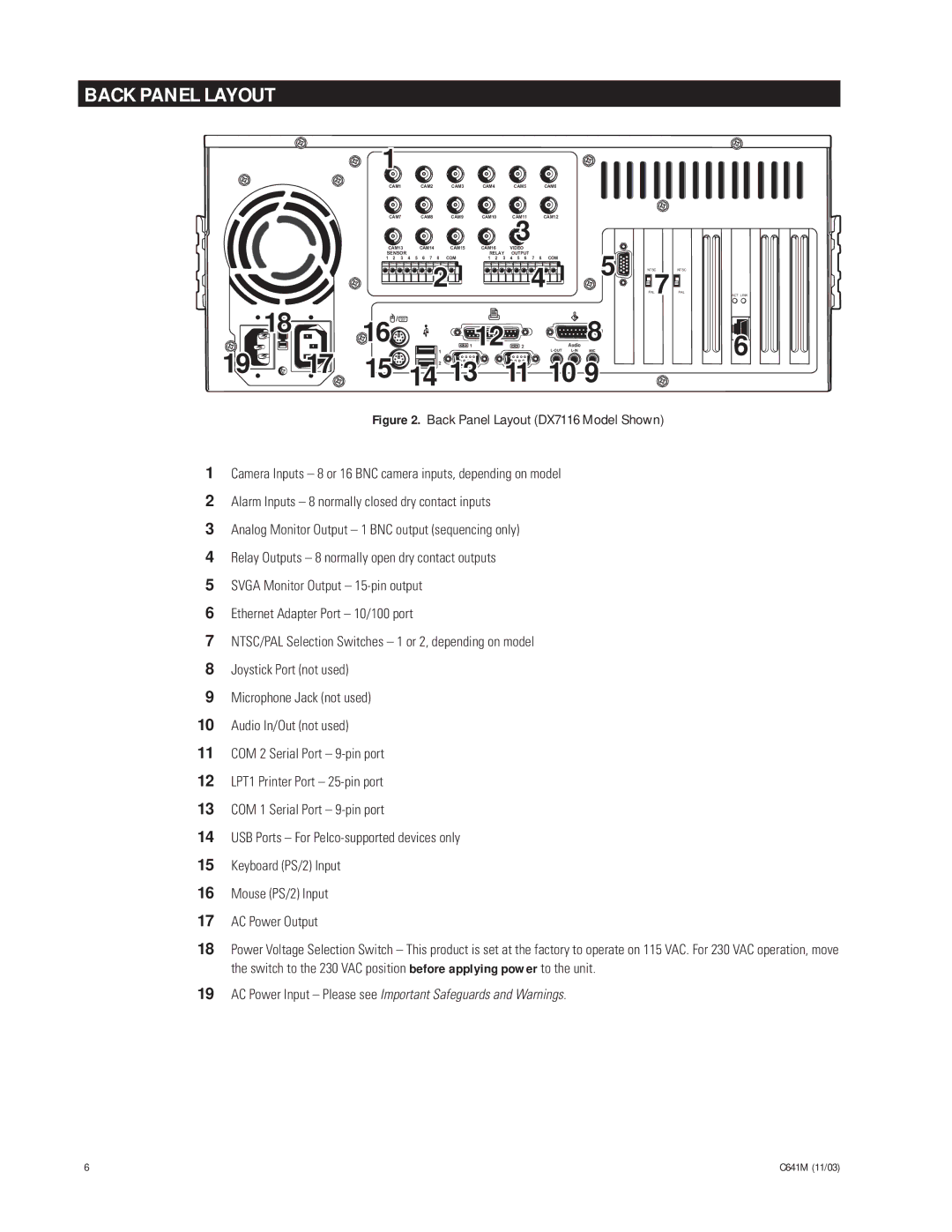
Figure 2. Back Panel Layout (DX7116 Model Shown)
1Camera Inputs Ð 8 or 16 BNC camera inputs, depending on model
2Alarm Inputs Ð 8 normally closed dry contact inputs
3Analog Monitor Output Ð 1 BNC output (sequencing only)
4Relay Outputs Ð 8 normally open dry contact outputs
5SVGA Monitor Output Ð 15-pin output
6Ethernet Adapter Port Ð 10/100 port
7NTSC/PAL Selection Switches Ð 1 or 2, depending on model
8Joystick Port (not used)
9Microphone Jack (not used)
10Audio In/Out (not used)
11COM 2 Serial Port Ð 9-pin port
12LPT1 Printer Port Ð 25-pin port
13COM 1 Serial Port Ð 9-pin port
14USB Ports Ð For Pelco-supported devices only
15Keyboard (PS/2) Input
16Mouse (PS/2) Input
17AC Power Output
18Power Voltage Selection Switch Ð This product is set at the factory to operate on 115 VAC. For 230 VAC operation, move the switch to the 230 VAC position before applying power to the unit.
19AC Power Input Ð Please see Important Safeguards and Warnings.
6 | C641M (11/03) |