BASIC INSTALLATION
Basic installation covers all the equipment necessary to program and operate the system. Refer to the Extended Installation section for PTZ, alarm, sensors, and network connections.
Verify that the |
|
| |
voltage is set |
| Cameraer a CCDCColorr l CDSPP | |
| 7 | ||
correctly for |
| ||
your location |
| ||
115 |
|
| 6 |
OR | 230 |
|
|
|
|
| |
1 |
| NTSC | |
|
|
| |
| 2 | 3 | 4 PAL 5 |
|
|
| |
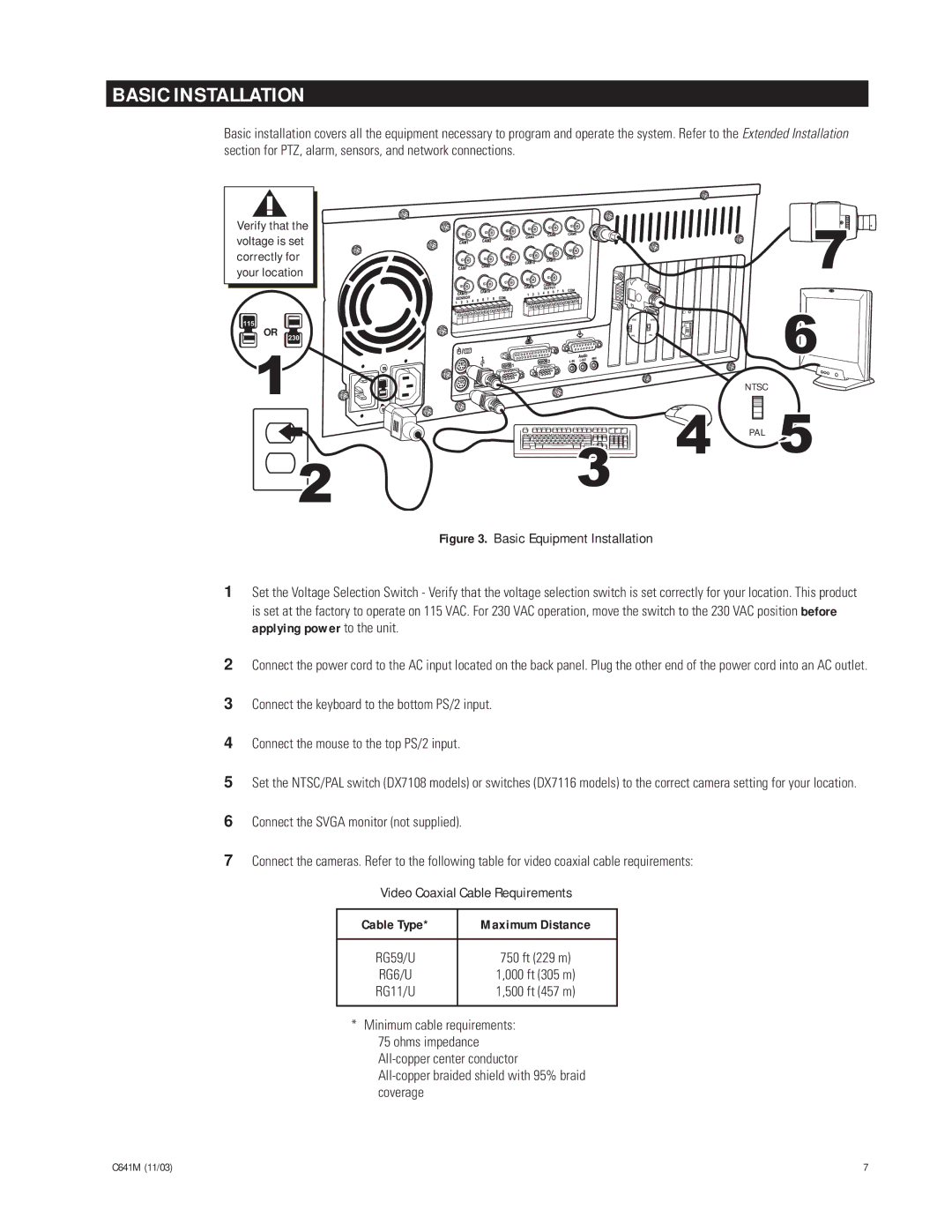
Figure 3. Basic Equipment Installation
1Set the Voltage Selection Switch - Verify that the voltage selection switch is set correctly for your location. This product is set at the factory to operate on 115 VAC. For 230 VAC operation, move the switch to the 230 VAC position before applying power to the unit.
2
3
4
5
6
7
Connect the power cord to the AC input located on the back panel. Plug the other end of the power cord into an AC outlet.
Connect the keyboard to the bottom PS/2 input.
Connect the mouse to the top PS/2 input.
Set the NTSC/PAL switch (DX7108 models) or switches (DX7116 models) to the correct camera setting for your location.
Connect the SVGA monitor (not supplied).
Connect the cameras. Refer to the following table for video coaxial cable requirements:
Video Coaxial Cable Requirements
Cable Type* | Maximum Distance |
|
|
RG59/U | 750 ft (229 m) |
RG6/U | 1,000 ft (305 m) |
RG11/U | 1,500 ft (457 m) |
|
|
*Minimum cable requirements: 75 ohms impedance
C641M (11/03) | 7 |