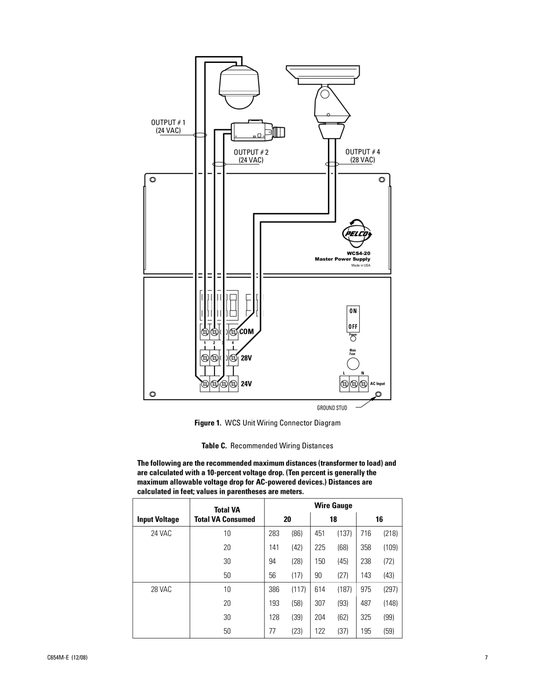
OUTPUT # 1
(24 VAC)
OUTPUT # | 2 | OUTPUT # | 4 |
(24 VAC) |
| (28 VAC) |
|
¨
Master Power Supply
Made in USA
|
|
|
| O N |
|
|
| COM | O F F |
|
|
| Power | |
1 | 2 | 3 | 4 |
|
|
|
|
| Main |
|
|
| 28V | Fuse |
|
|
|
|


 24V
24V
LN
AC Input
GROUND STUD
Figure 1. WCS Unit Wiring Connector Diagram
Table C. Recommended Wiring Distances
The following are the recommended maximum distances (transformer to load) and are calculated with a
|
| Total VA |
|
| Wire Gauge |
|
|
| |
|
|
|
|
|
|
|
|
| |
| Input Voltage | Total VA Consumed |
| 20 |
| 18 |
| 16 |
|
|
|
|
|
|
|
|
|
|
|
| 24 VAC | 10 | 283 | (86) | 451 | (137) | 716 | (218) |
|
|
| 20 | 141 | (42) | 225 | (68) | 358 | (109) |
|
|
| 30 | 94 | (28) | 150 | (45) | 238 | (72) |
|
|
| 50 | 56 | (17) | 90 | (27) | 143 | (43) |
|
|
|
|
|
|
|
|
|
|
|
| 28 VAC | 10 | 386 | (117) | 614 | (187) | 975 | (297) |
|
|
| 20 | 193 | (58) | 307 | (93) |
| (148) |
|
|
| 487 |
| ||||||
|
| 30 | 128 | (39) | 204 | (62) | 325 | (99) |
|
|
| 50 | 77 | (23) | 122 | (37) | 195 | (59) |
|
|
|
|
|
|
|
|
|
|
|
|
|
|
|
|
| 7 | |||