POWER AND VIDEO CONNECTIONS
To connect the camera power and video do the following:
1.Remove the rear cover from the camera (refer to Figure 1). Thread cabling through the rear cover.
2.Connect the power cable to the two pin power connector on the back of the camera using the terminal block connector provided. Refer to Table A for the recommend wire gauge to use for the installation.
3.Connect a video cable to the SIGNAL OUT connector (BNC) on the back of the camera. Refer to Table B for the type of video coaxial cable to use.
4.Reattach the rear cover to the back of the camera.
Power Connections
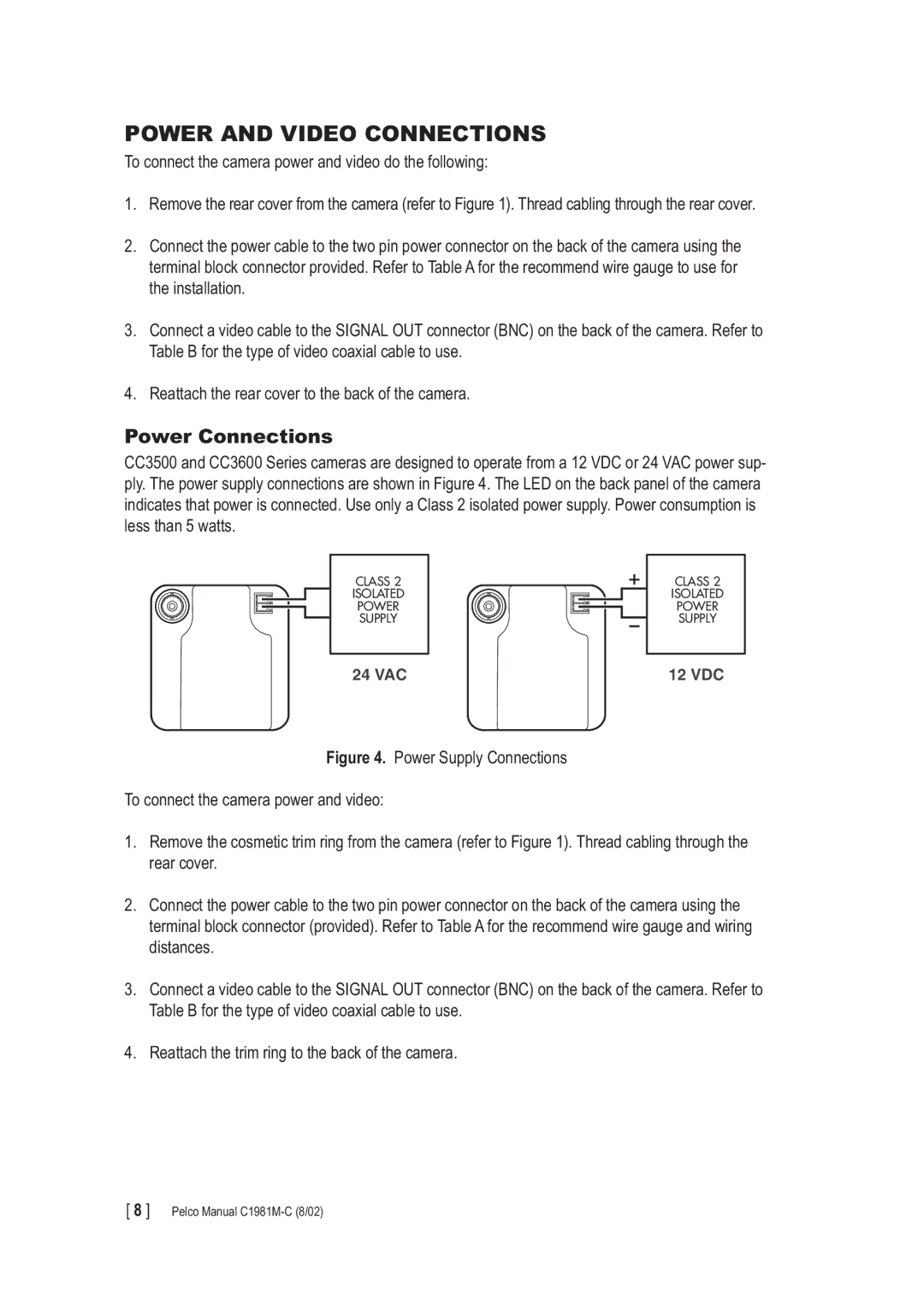
CC3500 and CC3600 Series cameras are designed to operate from a 12 VDC or 24 VAC power sup- ply. The power supply connections are shown in Figure 4. The LED on the back panel of the camera indicates that power is connected. Use only a Class 2 isolated power supply. Power consumption is less than 5 watts.
CLASS 2
ISOLATED
POWER
SUPPLY
CLASS 2
ISOLATED
POWER
SUPPLY
24 VAC | 12 VDC |