DX9000H-C, DX9000H-C SERIES specifications
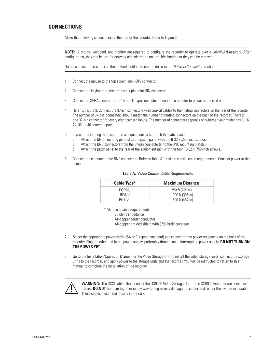
The Pelco DX9000H-C Series represents a significant advancement in the realm of digital video recorders (DVRs), designed specifically for the challenges of modern surveillance environments. This series is synonymous with reliability, high-quality video recording, and versatile integration capabilities, making it a popular choice for security professionals across various sectors.One of the main features of the DX9000H-C series is its exceptional recording capabilities. It supports a variety of video resolutions, ensuring crisp and clear images. With the ability to record in high definition, the DX9000H-C is perfect for environments where detail is crucial, such as retail, banking, and transportation. Its extensive storage options also enable users to store significant amounts of footage, utilizing both internal and external storage solutions, which can be crucial for meeting regulatory compliance.
In terms of technology, the DX9000H-C series employs advanced video compression techniques, such as H.264, which significantly reduces file sizes without compromising quality. This ensures efficient use of storage space and improves data transfer speeds when accessing video remotely. The system is also equipped with a robust array of connectivity options, including network interfaces that facilitate seamless integration into existing surveillance systems, making it a versatile choice for any security setup.
Another standout characteristic of the DX9000H-C series is its user-friendly interface. With an intuitive setup process and straightforward navigation, operators can quickly familiarize themselves with the system, which is critical in high-pressure environments. The intuitive user interface provides easy access to live feeds, playback footage, and system settings, enhancing operator efficiency and effectiveness in responding to incidents.
Furthermore, the DX9000H-C series includes features such as motion detection, alarm integration, and remote monitoring capabilities, allowing for proactive security management. These functionalities can significantly enhance threat detection and response times, offering a comprehensive security solution.
Overall, the Pelco DX9000H-C Series stands out for its combination of superior recording quality, advanced technology, and user-friendly design. It empowers security professionals to maintain a watchful eye over their assets, ensuring peace of mind in increasingly complex surveillance landscapes. Whether for small businesses or large enterprises, the DX9000H-C series is a reliable and efficient solution for modern security needs.

