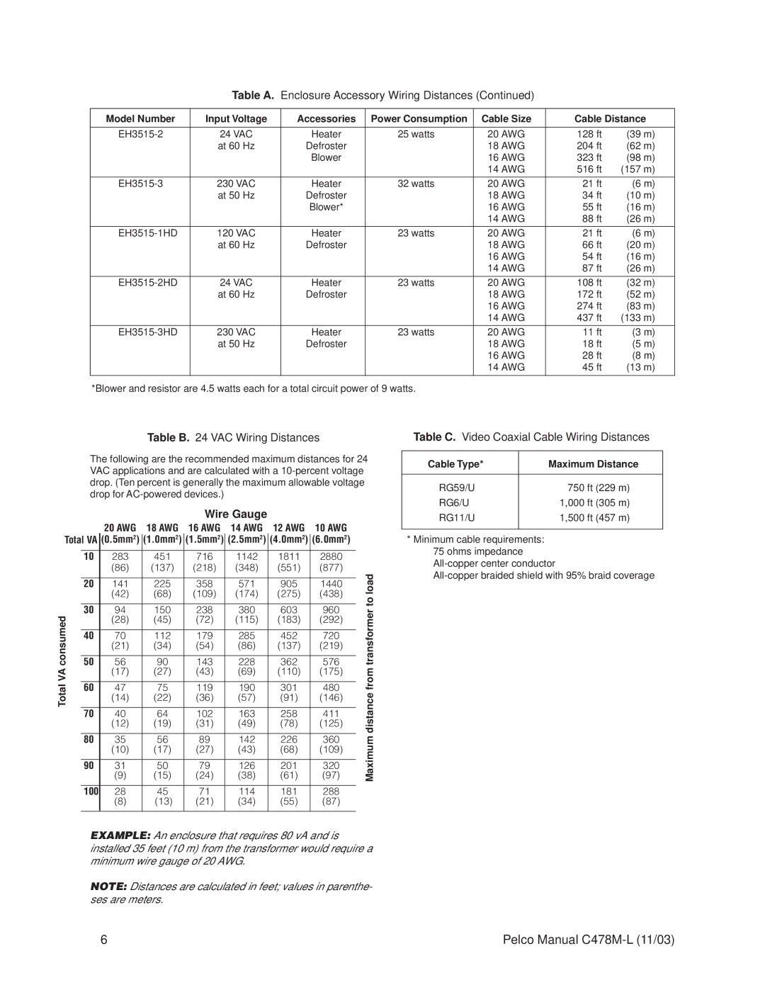
EH3515, EH3512 specifications
The Pelco EH3515 and EH3512 are cutting-edge outdoor surveillance camera housings designed specifically for professional security systems. Known for their rugged construction and reliable performance, these models meet the demands of various surveillance applications in both urban and rural settings.One of the standout features of the EH3515 and EH3512 is their robust design. Constructed from high-quality aluminum and equipped with an integrated heater and blower, these housings ensure optimal camera operation even in harsh weather conditions. They are rated for IP66 environmental protection, which guards against dust and powerful water jets, making them suitable for diverse environmental challenges.
Both models are designed to accommodate a variety of CCTV cameras, allowing for significant flexibility in surveillance setups. The EH3515 supports larger camera sizes, while the EH3512 is tailored for more compact camera systems, making them ideal for organizations looking to customize their security experience. Their versatile mounting options enable installation on walls, ceilings, or even poles, making them adaptable to various locations and arrangements.
Additionally, the EH3515 and EH3512 feature an adjustable mounting bracket, which simplifies the installation process and provides versatile positioning options. This adaptability allows users to easily adjust camera angles to achieve optimal field of view, ensuring comprehensive coverage of monitored areas.
The housings also come with a clear, tempered glass front to protect internal cameras from scratches and other damage, while also allowing for excellent visibility. This feature is essential for maintaining the integrity of surveillance footage. Furthermore, the models are designed to support infrared lighting, enabling effective night-time surveillance, which enhances security in low-light conditions.
Both models are fully compatible with Pelco’s extensive suite of video management solutions, allowing for seamless integration into existing systems. This compatibility ensures that users can take full advantage of advanced features such as remote monitoring and image enhancement technologies.
In summary, the Pelco EH3515 and EH3512 are superior outdoor camera housings that combine durability, flexibility, and ease of installation. With their weather-resistant design, compatibility with various cameras, and advanced protective features, they stand out as essential components for any effective security system. Organizations seeking reliable and high-quality surveillance solutions will find these models meet and exceed their requirements.
