C1463M-A (12/00)
PDF8 Series
Pendant Fixed Mount Dome
®
3500 Pelco Way
Clovis, CA
USA
In North America & Canada:
Tel (800)
FAX (800)
DataFAX (800)
International Customers:
Tel +1(559)
FAX +1(559)
DataFAX +1(559)
PelcoEurope BV
Dillenburg Center
Dillenburgstraat 5F
5652 AM Eindhoven
The Netherlands
Tel +31(40)
FAX +31(40)
Pelco Online
www.pelco.com
IMPORTANT SAFEGUARDS AND WARNINGS
Prior to installation and use of this product, the following WARNINGS should be observed.
1.Installation and servicing should only be done by qualified service personnel and conform to all local codes.
2.Unless the unit is specifically marked as a NEMA Type 3, 3R, 3S, 4, 4X ,6 or 6P enclosure, it is designed for indoor use only and it must not be installed where exposed to rain and moisture.
3.Only use replacement parts recommended by Pelco.
4.The installation method and materials should be capable of supporting four times the weight of the enclosure, pan/tilt, camera and lens combination.
Please thoroughly familiarize yourself with the information in this manual prior to installation and operation.
DESCRIPTION
PDF8 Series domes are pendant style units designed for indoor use only. The dome can be mounted to a ceiling or wall using a suitable length pipe (threaded at both ends) and a mount/ adapter. All PDF8 Series pendant domes are compatible with Pelco IWM Series Wall Mount, the MRWA Wall Mount, and the MRCA Ceiling Mount.
Models
Pendant dome with opaque black bubble and smoked viewing slot (1/2 | |
| of light loss) |
Same as the |
INSTALLATION
Mount, Back Box Cap and Back Box Installation
NOTE: The length of pipe used may cause noticeable motion on the video display. If this occurs, the pipe will require additional support by bracing, guy wires, etc.
CAUTION: The mount area must be capable of supporting up to 40
pounds (18.12 kg) of weight.
1Refer to the instructions supplied with the IWM, MRWA, or MRCA to install the mount for the PDF8 Series dome. Bring the wiring for the dome through the mount. Refer to Tables A and B for wir- ing distances.
2Install a threaded pipe with a minimum length of
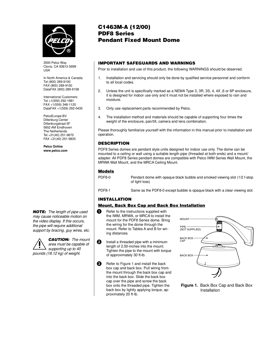
3Refer to Figure 1 and install the back box cap and back box. Pull wiring from the mount through the back box cap and into the back box. Slide the back box cap over the pipe and screw the back box onto the threaded pipe. Tighten the back box by lightly applying torque, ap- proximately 20
MOUNT
PIPE
(NOT SUPPLIED)
BACK BOX
CAP
BACK BOX
