ADDITIONAL REMOTE CONTROL IN LIEU OF CLEANER:
If the system does not utilize aseparate pool cleanerpum~it is possible to use the pool cleaner relay to activate an additional remote circuit This circuit is controlled by the
NOTE: CLNR Program Button on the Time Master Controller will be redundant. Flag and Status Light may still be turned ON, but display is meaningless.
Adjust U1O Program Switch (located at the bottom of the printed circuit board) so that Switches #4, # 5 and # 6 are programmed ON, and Switches #1, #2, #3 and #7 are programmed OFF.
Modify low voltage wiring as follows
Disconnect black wire of blklyel pair from CLNR screw terminal on
SPA WATERFALL CONTROL:
For systems where spa water level is higher than that of the pooh a Spa Waterfall Control (model
AUXl Button at theTime Master or an optional Remote Control switch can be used to rotate the return valve operator to SPA position while system is in POOL mode, thus creating an overflow(waterfall effect) from spa to pool This effect will ceasewhenever the system is in SPA mode.
Install
ELECTRIC HEATER CONTROL:
For systems which utilize a heat pump or electric heater in lieu of a gas heater, a Relay Kit (model
FREEZE SENSOR:
A Recirculating Freeze Sensor(mode1
An Auxiliary Pump Freeze
CUSTOM OPTIONS:
Additional custom options are also available. These options, however, require custom adjustments at the factory.
Consult Compool Corporation for details.
SAVE THESE INSTRUCTIONS
HIGH VOLTAGE WIRING:
All high voltage connections are made to terminal blocks, which are located b e hind service panel in right side compartment of
A high voltage wiring label is located adjacent t o terminal blocks. Knock out holes are provided on bottom of enclosure for conduit mounting.
Provide a separate circuit breaker (if possible) to power the system. Either 115VAC or 230VAC can be used System draws less than 1 amp. Runwires from circuit breaker to high voltage compartment of
Provide independent circuit breakers(if possible) for FLTR, CLNR, and AUX 1.
Note: AUX 2,"AUX 3, and AUX 4 are optional and require additional relay kits (model
Run wires from breakers to high voltage compartment of
Connect pumps and other high voltage equipment to LOAD 1 and LOAD2 terminals at relevant terminal blocks Each individual terminal blockcan be wired for either 115 or 230V AC. A relay allocation chart is provided inside enclosure cover for the service man'sconvenience
To reduce the risk of electric shock provide a continuous green insulated copper wire, no smaller than #12 AWG between grounding bus of
A wire connector is provided for bonding to local ground points To further reduce the risk of electric shock this connector should be bonded with a #8 AWG copper wire to any metal ladders, water pipes, or other metal within 5 feet of pool or spa
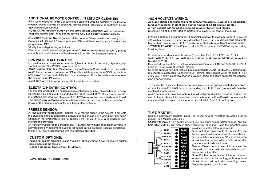
TIME MASTER:
Select a convenient location inside the house or other
Unscrew faceplate from enclosure, and use enclosure as a template to mark and cut hole ( 8%" wide by 4%" high) in sheetrock or wall panel in^ Using the mounting clips
provided, install enclosure into wall.
Strip jacket of 6pair cable 6" to identify the twisted pairs and assure correct connections Strip insulation of each wire l/4" and connect to screw terminal in accordance with wiring dia- gram located inside enclosure.
Caution: Do not untwist pairs It is necessary to retain wires in pairs so that appropriate connec- tions can be identified
Note: For the convenience of the sewiceman
'screw terminal can be unplugged from printed circuit board without disconnecting wires Mount faceplate to enclosure.