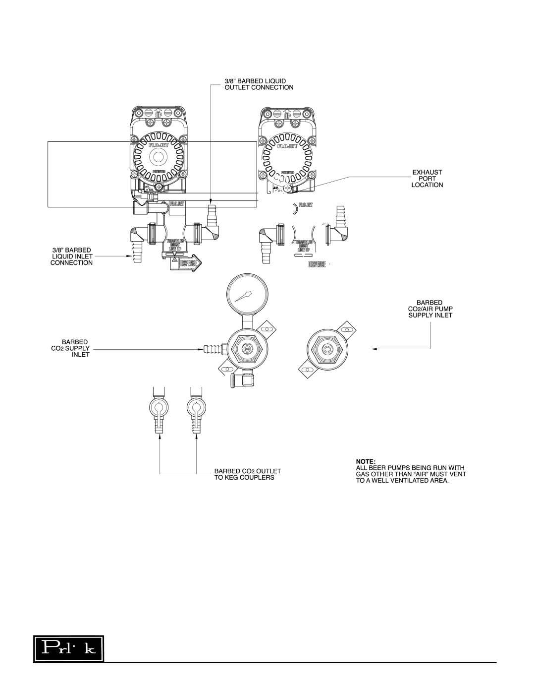
How to Operate – Beer Pump Panels

Adjust primary CO2 regulator by turning adjusting screw counterclockwise until it turns freely, then turn hand valve counterclockwise on CO2 cylinder to the fully open position. Next, turn regulator adjusting screw clockwise until desired pressure is reached.

Note: If CO2 is only being used for keg- applied pressure, adjust to approximately 40 psig. If CO2 is being used to supply beer pumps, adjust to the required system pressure plus an additional 15 psig.

Adjust the air compressor output regulator pressure to a minimum of 15 psig. greater than the maximum required system pressure required to operate the beer pumps. Maximum setting 100 psig.

Adjust secondary CO2 regulator which supplies the keg pressure located on the beer pump panel to the proper pressure setting. Setting depends on beer brand and temperature. Desired goal is to maintain the natural carbonation in the beer. Open the shut- off valves.

Ensure the Probe Valve on the Perlick Smart Coupler is in closed position. See figure 1. Ensure the Beer Pump Flow Reversal/Dispense handle is in the dispense position. Adjust the Secondary Air/ CO2 regulator located on the beer pump panel to a minimum operating pressure of 10 psig.

Connect the coupler to a regulated water supply with pressure less than 30 psig. Note: Pump damage may occur with pressure higher than 30 psig.

Open the water supply. Then open probe valve on Perlick Smart coupler to the 45° position. See figure 2. The beer pump will slowly pump up the beer line in the trunk housing to set psig. Note: If pump continues to run for longer than expected, check lines for possible leaks at one or more of the connections.

Gradually increase secondary regulator pressure to the designed system pressure to achieve a flow rate of one gallon per minute from the dispensing head. Note: Maximum beer pump operating pressure is 90 psig.

Open dispensing head faucet to purge air trapped within the tubing.

Check all gas and liquid line fittings and connections for leaks.

Close probe valve on Perlick Smart Coupler. (See figure 1) and disconnect coupler from regulated water source.

Clean beer system. After cleaning and rinsing the system, make sure the beer line is full of cold water (beer dispensing from warm beer lines will be poor quality).

Tap fresh keg with Perlick Smart Coupler. Open dispensing head faucet until clear beer flows.

Smart Coupler Probe Valve Lever Positions

Figure 1

Figure 2

Figure 3

Closed Position

45° or Cleaning Position

Open Position

Perlick is committed to continuous improvement. Therefore, we reserve the right to change specifications without prior notice.

4

Page 4
Image 4
Perlick 63134-3, 63134-2, 63134-1, 63134-4 manual How to Operate Beer Pump Panels, Smart Coupler Probe Valve Lever Positions

63134-4, 63134-1, 63134-2, 63134-3 specifications

The Perlick 63134 series of products, including models 63134-1, 63134-2, 63134-3, and 63134-4, are engineered for excellence in beverage dispensing solutions. Perlick is known for its commitment to quality and innovation in the commercial beverage space, and this series exemplifies that reputation.

One of the standout features of the 63134 series is its advanced design that ensures optimal performance in various settings, including bars, restaurants, and kitchens. These models are crafted with stainless steel exteriors, providing both durability and a sleek aesthetic that blends seamlessly into modern environments. The stainless steel also aids in maintaining hygiene, an essential aspect of food and beverage service.

Each model in the series comes equipped with innovative cooling technologies, such as the Perlick exclusive patented design that allows for rapid cooling and efficient temperature control. This means beverages are served at the ideal temperature every time, enhancing customer satisfaction. Additionally, the integrated draft beer system is designed to minimize waste, ensuring that every pour is precise, reducing foam and spillage.

The 63134 series offers an impressive storage capacity, making them suitable for high-volume operations. The spacious interiors are designed to accommodate a wide range of beverages efficiently, making it easy to organize and access product. Configurable internal shelving allows for customization, ensuring that businesses can tailor the unit to their specific needs.

Ergonomics also play a pivotal role in the design of the 63134 models. Features such as self-closing doors with a magnetic seal enhance efficiency, while the tall and wide openings ensure easy access to the contents. Furthermore, the included LED lighting enhances visibility, making it easy for staff to quickly locate items even in dimly lit environments.

In terms of energy efficiency, the Perlick 63134 series is designed with sustainability in mind. These models are built to consume less energy while providing outstanding performance, which translates to lower operating costs for businesses.

In summary, the Perlick 63134 series, including models 63134-1, 63134-2, 63134-3, and 63134-4, represents the pinnacle of beverage dispensing technology. With features focusing on design, efficiency, and user-friendliness, these models are ideal for any establishment looking to elevate its beverage service and provide an exceptional experience for customers. Quality, performance, and reliability are the hallmarks of the Perlick 63134 series.