INSTALLATION andTAPPING
PARTYMASTER DISPENSER
Connecting the Keg Coupler (when supplied by Perlick)
1.Place one brown leather washer into black beer line connector hose on hex nut
side. Screw connector to stainless steel beverage line on faucet standard. Tighten with a wrench, but do not over tighten.
2.Make sure lever handle on keg coupler is in the UP (untapped) position. Place one brown leather washer into wing nut end of black beer line connector hose and thread onto top of keg coupler. Hand tighten.
3.Place clamp on one end of red air line. Push end over air valve located inside cabinet. Tighten clamp with screwdriver. Turn
4.Place clamp on the other end of red air line and push over tailpiece on coupler. Tighten clamp with screwdriver.
CAUTION: DO NOT USE KEG COUPLER AS A HANDLE TO LIFT KEG.
Tapping a Single Valve Keg (Sankey)
Single Valve Keg Coupler
1.Be sure beer faucet is in closed position.
2.Align keg lugs with lug openings on bottom of coupler.
3.Turn clockwise, 1/4 turn. Pull handle out and down. Keg is now tapped.
4. Open
Important Note: Be sure to close this valve when untapping keg.
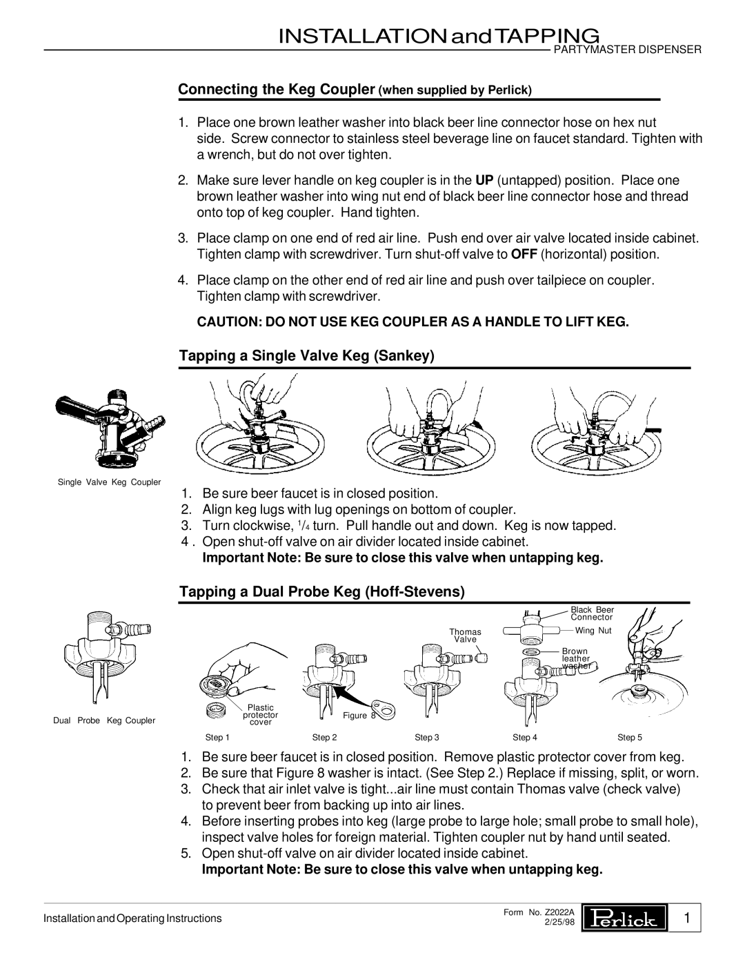
Tapping a Dual Probe Keg (Hoff-Stevens)
|
|
|
|
| Black Beer | |
|
|
|
|
| Connector | |
|
|
|
| Thomas |
| Wing Nut |
|
|
|
|
| ||
|
|
|
| Valve |
|
|
|
|
|
|
| Brown | |
|
|
|
|
| leather | |
|
|
|
|
| washer | |
| Plastic |
|
|
|
|
|
Dual Probe Keg Coupler | protector |
| Figure 8 |
|
|
|
cover |
|
|
|
|
| |
| Step 1 | Step 2 | Step 3 | Step 4 |
| Step 5 |
1.Be sure beer faucet is in closed position. Remove plastic protector cover from keg.
2.Be sure that Figure 8 washer is intact. (See Step 2.) Replace if missing, split, or worn.
3.Check that air inlet valve is tight...air line must contain Thomas valve (check valve) to prevent beer from backing up into air lines.
4.Before inserting probes into keg (large probe to large hole; small probe to small hole), inspect valve holes for foreign material. Tighten coupler nut by hand until seated.
5.Open
Important Note: Be sure to close this valve when untapping keg.
Installation and Operating Instructions
Form No. Z2022A 2/25/98
1