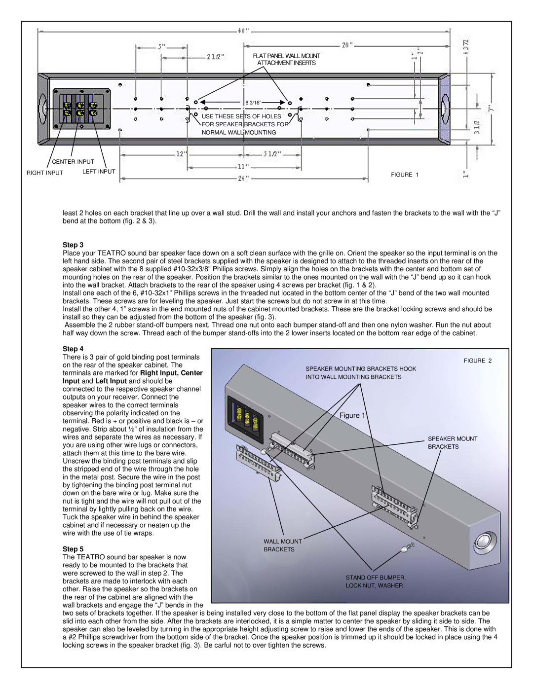
PC-3.0, V-3.0 specifications
Phase Technology has made a significant impact in the realm of audio technology with its release of the V-3.0 and PC-3.0 models. These home audio solutions are designed to deliver exceptional sound quality, making them popular among audiophiles and casual listeners alike.The V-3.0 is a versatile speaker that embodies cutting-edge technology and attention to detail. One of its standout features is the incorporation of a precision-crafted cabinet that helps minimize resonance, ensuring a clear and accurate sound reproduction. Additionally, the V-3.0 benefits from a unique driver design that includes a newly engineered diaphragm to enhance response and imaging capabilities. With a frequency response range that extends well beyond most dedicated music systems, the speakers are able to capture the nuances in various sound profiles, whether it be classical music or modern rock.
On the other hand, the PC-3.0 is designed as a powerful companion to the V-3.0. This subwoofer features advanced bass technology that provides deep, robust low frequencies without overwhelming the overall sound field. Its high-efficiency amplifier produces a potent output while maintaining clarity and control over the bass spectrum. The PC-3.0 also features a customizable crossover setting, allowing users to easily tailor the low-end response to match their unique room acoustic needs.
Both the V-3.0 and PC-3.0 utilize proprietary Phase Technology innovations, including the company's patented Quadra-Elliptical™ speaker technology. This technology is central to delivering more consistent and accurate sound across a wider listening area, making the speakers forgiving in terms of placement. Whether they are set up in a dedicated listening room or a more casual environment, the speakers maintain their performance capabilities.
Furthermore, Phase Technology emphasizes ease of installation and compatibility with a variety of home theater systems. Their products come with a robust range of connectivity options, ensuring seamless integration with modern audio setups. This approach underscores Phase Technology's commitment to enhancing the overall user experience with their products.
In summary, the Phase Technology V-3.0 and PC-3.0 offer audio enthusiasts a combination of advanced technology, exceptional sound quality, and flexible integration options. With their precise cabinet designs, innovative driver technology, and powerful performance, they stand as a benchmark in the home audio market, pushing the boundaries of what consumers can expect from their audio experiences.

