Product Information |
| |
• System MTBF | 50K hrs (CCFL 40Khrs) | |
• Cabinet color | 150P2M: Light Gray | |
150P2G: Black | ||
|
* These information are subject to change without notice.
RETURN TO TOP OF THE PAGE
Pin Assignment
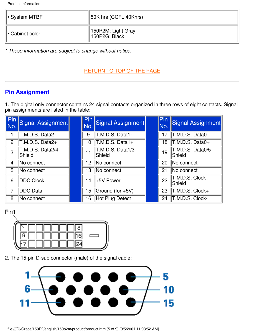
1.The digital only connector contains 24 signal contacts organized in three rows of eight contacts. Signal pin assignments are listed in the table:
|
|
|
|
|
|
|
|
|
|
|
|
|
|
|
Pin |
| Signal Assignment |
| Pin |
| Signal Assignment |
| Pin |
| Signal Assignment | ||||
No. |
|
|
|
|
| No. |
|
|
|
|
| No. |
|
|
1 |
| T.M.D.S. Data2- |
|
| 9 |
| T.M.D.S. Data1- |
|
| 17 |
| T.M.D.S. Data0- | ||
2 |
| T.M.D.S. Data2+ |
|
| 10 |
| T.M.D.S. Data1+ |
|
| 18 |
| T.M.D.S. Data0+ | ||
3 |
| T.M.D.S. Data2/4 |
|
| 11 |
| T.M.D.S. Data1/3 |
|
| 19 |
| T.M.D.S. Data0/5 | ||
| Shield |
|
|
| Shield |
|
|
| Shield | |||||
4 |
| No connect |
|
| 12 |
| No connect |
|
| 20 |
| No connect | ||
5 |
| No connect |
|
| 13 |
| No connect |
|
| 21 |
| No connect | ||
6 |
| DDC Clock |
|
| 14 |
| +5V Power |
|
| 22 |
| T.M.D.S. Clock | ||
|
|
|
|
|
|
| Shield | |||||||
7 |
| DDC Data |
|
| 15 |
| Ground (for +5V) |
|
| 23 |
| T.M.D.S. Clock+ | ||
8 |
| No connect |
|
| 16 |
| Hot Plug Detect |
|
| 24 |
| T.M.D.S. Clock- | ||
|
|
|
|
|
|
|
|
|
|
|
|
|
|
|
2. The
file:///D/Grace/150P2/english/150p2m/product/product.htm (5 of 9) [9/5/2001 11:08:52 AM]