170B4BG/170B4BB/170B4BS Product Information |
|
|
|
|
|
|
|
| ||||||
|
|
|
|
|
|
|
|
|
|
|
|
|
|
|
1 |
| T.M.D.S. Data2- |
|
| 9 |
| T.M.D.S. Data1- |
|
| 17 |
| T.M.D.S. Data0- | ||
2 |
| T.M.D.S. Data2+ |
|
| 10 |
| T.M.D.S. Data1+ |
|
| 18 |
| T.M.D.S. Data0+ | ||
3 |
| T.M.D.S. Data2/4 |
|
| 11 |
| T.M.D.S. Data1/3 |
|
| 19 |
| T.M.D.S. Data0/5 | ||
| Shield |
|
|
| Shield |
|
|
| Shield | |||||
4 |
| No connect |
|
| 12 |
| No connect |
|
| 20 |
| No connect | ||
5 |
| No connect |
|
| 13 |
| No connect |
|
| 21 |
| No connect | ||
6 |
| DDC Clock |
|
| 14 |
| +5V Power |
|
| 22 |
| T.M.D.S. Clock | ||
|
|
|
|
|
|
| Shield | |||||||
7 |
| DDC Data |
|
| 15 |
| Ground (for +5V) |
|
| 23 |
| T.M.D.S. Clock+ | ||
8 |
| No connect |
|
| 16 |
| Hot Plug Detect |
|
| 24 |
| T.M.D.S. Clock- | ||
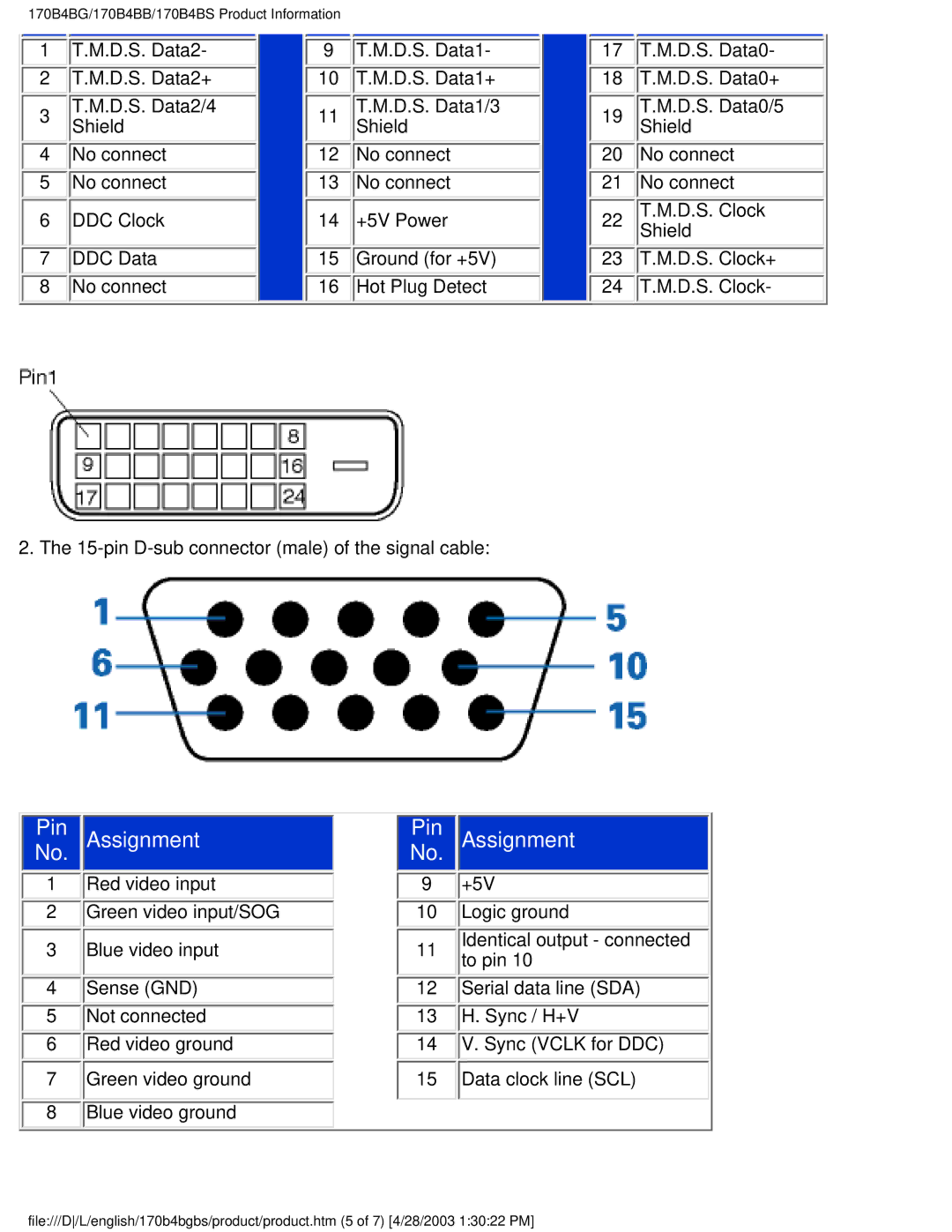
2. The
|
|
|
|
|
|
|
Pin |
| Assignment | Pin |
| Assignment | |
No. |
|
|
| No. |
|
|
1Red video input
2Green video input/SOG
3Blue video input
4Sense (GND)
5Not connected
6Red video ground
7Green video ground
8Blue video ground
9 +5V
10Logic ground
11Identical output - connected to pin 10
12Serial data line (SDA)
13H. Sync / H+V
14V. Sync (VCLK for DDC)
15Data clock line (SCL)
file:///D/L/english/170b4bgbs/product/product.htm (5 of 7) [4/28/2003 1:30:22 PM]