For fast help, call us first
Warranty Verification
Important Safety Instructions
Table of Contents
Standard Broadcast VHF/UHF or Cable TV Catv channel capabil
Features
Adjusting the Picture
Press the STATUS/EXIT button
Turning on the Dynamic Noise Reduction Control
Turning on the Imagemax Control
Press the STATUS/EXIT but- ton to remove the menu from
Using the Closed Captioning Control
Press the Cursor Right button and the menu will shift to
Press the STATUS/EXIT but
Selecting the Screen Format Size
Press the Cursor Down
Press the Cursor Right
Press the STATUS/EXIT but
Activating the Blue Mute Control
Press the Menu button on
Press the Cursor Right
Sleep OFF
Using the Sleep Timer
Press the Cursor Right but
Timer Setting the Clock
Press the Cursor UP or CUR- SOR Down button to select
Timer Setting the Start Time
Timer Setting the Stop Time
Channel. Or, press the Cursor
Timer Selecting the Channel
Press the Numbered but
Once press the Cursor
Timer Setting Activate to on or OFF
Or Cursor Left button to turn
Timer Turning on the Timer Display
Then press the Cursor Down
You also can block individual channels or block programming
Understanding Autolock
Code
Autolock Setting UP the Access Code
Left. Then press the Cursor
Autolock Blocking Channels
Cursor Down button to high
Enter your four-digit Access CODE. Correct will
Auto Lock Blocking by Movie Rating
Button again to highlight
Autolock Blocking by TV Rating
Press the Cursor Right or
Access Code and the menu
Autolock Turning Block on or OFF
Enter your four-digit
Or Cursor Left button to
Enter your four-digit Access Code and the menu
Autolock Blocking Unrated Broadcasts
Or Cursor Left button to tog
Enter your four-digit Access
Autolock Blocking Broadcasts That have no Rating
Block Unrated No Rating
Autolock Reviewing Your Settings
Auto Lock Viewing Blocked Programming
Control, press the Cursor
Sound Adjusting the Treble , Bass , and Balance
Cursor Left button to adjust
Use the Cursor Right or
Volume
Sound Adjusting the Volume
SOR Right or Cursor Left
Sound Using the AVL Audio Volume Leveler
Press the INCR. SURR. but
Sound Using Incredible Surround
Treble
Sound Setting the TV for Stereo and SAP
Audio OUT
Sound Setting the Audio OUT Control
Treble
Sound Using the TV Speaker Control and Audio Output Jacks
Sound Using the Surround Sound External Speaker Connections
Press the Source button
Sound Using the AUDIO/VIDEO Input Jacks
Super-Video connection on the rear of the TV can pro
Sound Using the AUDIO/VIDEO Input Jacks CONT’D
Device to the Y, Pb, Pr input jacks on the TV
Press the Picture button repeatedly to select either PER
Remote Control Using Autopicture
Press the Picture button
Press the Sound button
Remote Control Using Autosound
Press the Sound button on
Screen, press the Cursor
Remote Control Using Channel Surf
Press the CHANNEL+ or Ð
Press the Surf button on
Connect the Video OUT jack
First, use an optional signal
PIP Basic Connections
AV1, AV2, AV3, S-VIDEO Ð for
PIP Selecting the Signal Source
PIP Remote Control Buttons
Press the Cursor Right or Cursor Left button to
PIP Adjusting the Color and Tint
Cursor Left button to
Cable Box and VCR Connections
PIP More Connections
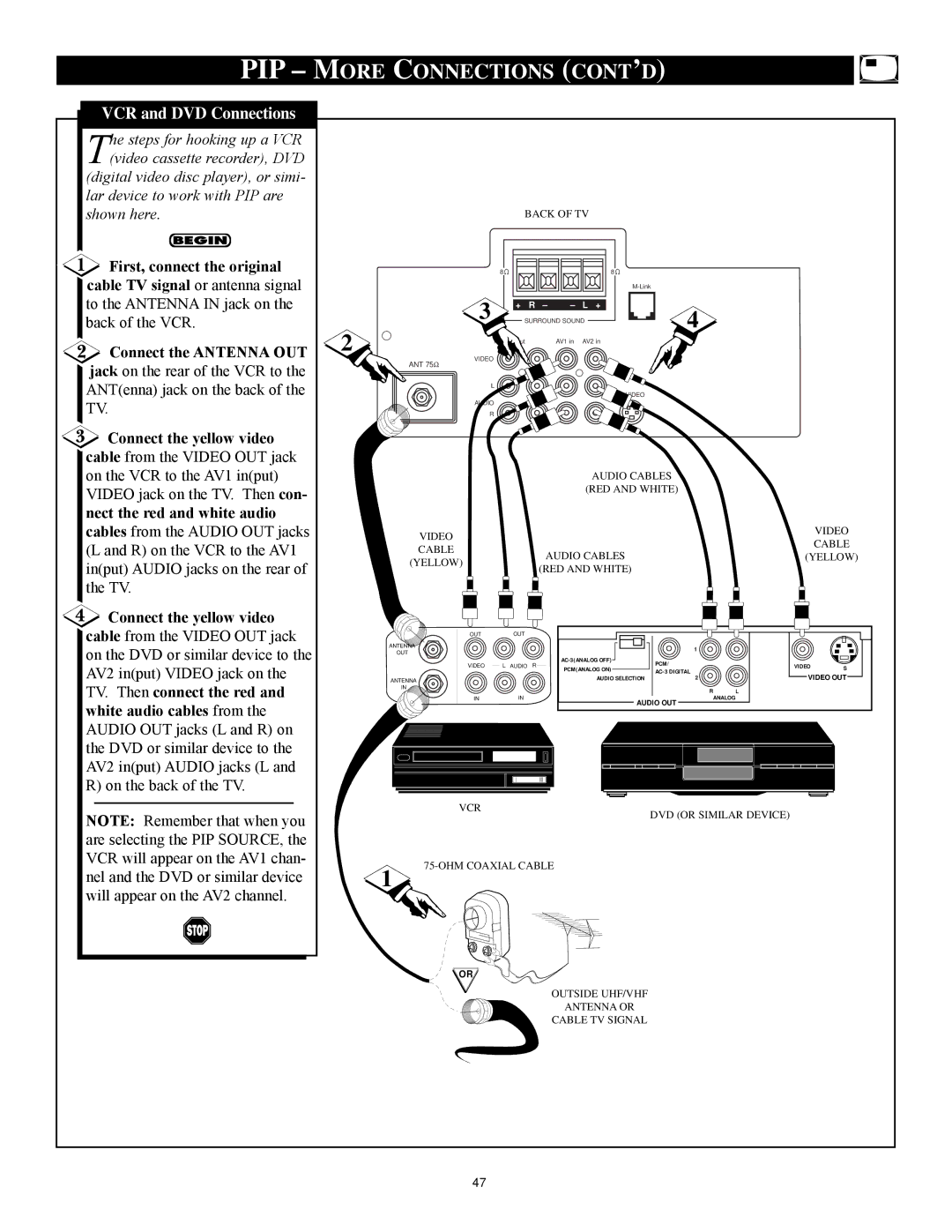
PIP More Connections Cont ’D
Troubleshooting
No Power No Picture No Sound
Glossary of Television Terms
Index
Canada
Factory Service Locations
Limited Warranty

