Philips SemiconductorsProduct data
|
|
| CBT6800 | |||||||
for live insertion |
|
|
|
|
|
| ||||
|
|
|
|
|
|
|
| |||
|
|
|
|
|
|
|
|
|
| |
AC CHARACTERISTICS |
|
|
|
|
|
|
|
| ||
GND = 0 V; CL = 50 pF; tr = tf ≤ 2.5 ns |
|
|
|
|
|
|
|
| ||
|
|
|
|
|
| LIMITS |
|
| ||
|
| FROM | TO |
|
|
|
| |||
SYMBOL | PARAMETER | VCC = +5.0 V | ±0.5 V | UNIT | ||||||
(INPUT) | (OUTPUT) | |||||||||
|
|
|
|
|
| Min |
| Max |
| |
|
|
|
|
|
|
|
|
|
| |
t | Propagation delay1 | A or B | B or A | — |
| .25 | ns | |||
pd |
|
|
|
|
|
|
|
|
| |
tPZH | BIASV = GND |
|
|
| A or B | 2.4 |
| 7.7 | ns | |
| ON | |||||||||
TPZL | BIASV = 3 V |
|
|
|
| 3.0 |
| 8.3 |
| |
tPHZ | BIASV = GND |
|
|
| A or B | 1.0 |
| 5.3 | ns | |
| ON | |||||||||
TPLZ | BIASV = 3 V |
|
|
|
| 3.1 |
| 7.8 |
| |
NOTE:
1.This parameter is warranted but not production tested. The propagation delay is based on the RC time constant of the typical
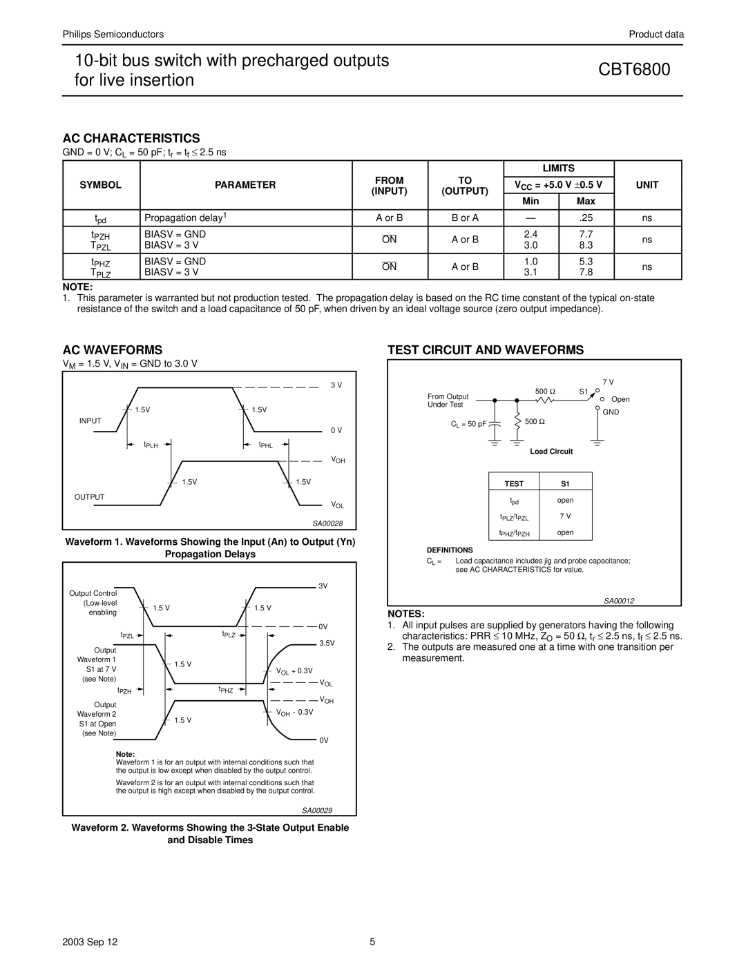
AC WAVEFORMS
VM = 1.5 V, VIN = GND to 3.0 V |
|
| 3 V |
1.5V | 1.5V |
INPUT |
|
| 0 V |
tPLH | tPHL |
| VOH |
1.5V | 1.5V |
OUTPUT | VOL |
| |
| SA00028 |
Waveform 1. Waveforms Showing the Input (An) to Output (Yn)
Propagation Delays
TEST CIRCUIT AND WAVEFORMS
|
| 7 V |
From Output | 500 Ω | S1 |
| Open | |
Under Test |
| |
| GND | |
|
| |
CL = 50 pF | 500 Ω |
|
|
| |
| Load Circuit | |
| TEST | S1 |
| tpd | open |
| tPLZ/tPZL | 7 V |
| tPHZ/tPZH | open |
DEFINITIONS
CL = Load capacitance includes jig and probe capacitance; see AC CHARACTERISTICS for value.
Output Control
tPZL ![]()
Output
Waveform 1
S1 at 7 V
(see Note)
tPZH
Output
Waveform 2
S1 at Open
(see Note)
1.5 V
tPLZ
1.5 V
tPHZ
1.5 V
3V
1.5 V
0V
3.5V
VOL + 0.3V
VOL
VOH
VOH - 0.3V
0V
SA00012
NOTES:
1.All input pulses are supplied by generators having the following characteristics: PRR ≤ 10 MHz, ZO = 50 Ω, tr ≤ 2.5 ns, tf ≤ 2.5 ns.
2.The outputs are measured one at a time with one transition per measurement.
Note:
Waveform 1 is for an output with internal conditions such that the output is low except when disabled by the output control.
Waveform 2 is for an output with internal conditions such that the output is high except when disabled by the output control.
SA00029
Waveform 2. Waveforms Showing the
and Disable Times
2003 Sep 12 | 5 |