BASIC TV TO VCR (& FRONT A/V INPUT) CONNECTIONS
TV TO VCR
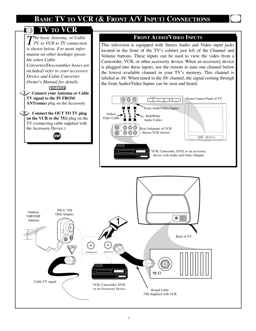
T he basic Antenna, or Cable TV, to VCR to TV connection is shown below. For more infor-
mation on other hookups (possi- ble when Cable Converter/Descrambler boxes are included) refer to your accessory Device and Cable Converter Owner's Manual for details.
BEGIN
FRONT AUDIO/VIDEO INPUTS
This television is equipped with Stereo Audio and Video input jacks located in the front of the TV’s cabinet just left of the Channel and Volume buttons. These inputs can be used to view the video from a Camcorder, VCR, or other accessory device. When an accessory device is plugged into these inputs, use the remote to tune one channel below the lowest available channel in your TV’s memory. This channel is labeled as AV. When tuned to the AV channel, the signal coming through the front Audio/Video Inputs can be seen and heard.
![]() Connect your Antenna or Cable TV signal to the IN FROM ANT(enna) plug on the Accessory.
Connect your Antenna or Cable TV signal to the IN FROM ANT(enna) plug on the Accessory.
![]() Connect the OUT TO TV plug on the VCR to the 75Ω plug on the
Connect the OUT TO TV plug on the VCR to the 75Ω plug on the
TV (connecting cable supplied with the Accessory Device.)
|
|
| MENU |
|
|
VIDEO |
| – VOLUME + | CHANNEL | POWER | |
L AUDIO R |
|
| |||
|
|
| Front Audio/Video Inputs | ||
Yellow |
|
| Red/White |
|
|
Video Cable |
|
|
|
| |
|
| Audio Cables |
| ||
|
|
|
| ||
ANTENNA | OUT | OUT | OUT |
|
|
IN |
|
|
|
|
|
| VIDEO |
| Rear Jackpanel of VCR |
| |
ANTENNA | L | AUDIO R |
|
| |
OUT |
|
| (Stereo VCR shown) |
| |
|
|
|
| ||
Front Control Panel of TV
IN | IN | IN |
VCR, Camcorder, DVD, or an accessory device with Audio and Video Outputs
Outdoor
300 to 75Ω
VHF/UHF
Ohm Adapter
Antenna | 1 |
|
OR
IN FROM ANT. | OUT TO TV |
75 V
Back of TV
75V
Cable TV signal
VCR, Camcorder, DVD, |
|
or an Accessory Device | Round Cable |
| |
| 75Ω Supplied with VCR |
7
