PFAM550 Manual.qxd 7/29/03 2:12 PM Page 7
Installation Procedure
PFAM550
Installation
It is recommended that assistance be available to safely install equipment in equipment racks. Chassis must be fastened securely in equipment rack before populating with modules.
1. | Install chassis in equipment rack (equipment rack sold separately) by |
| supporting the bottom and rear of PFAM550 at the desired elevation |
2. | in rack. |
Line up the side holes of chassis with the tapped equipment rack holes. |
3. Insert the provided screws through the side holes in chassis and thread into the tapped equipment rack holes.
4. Fasten the bottom screws first, then fasten top screws (tighten securely).
5. Install a short
6. Connect a cable from the output of the video source to the video
input connector of the PFAM550.
7. Connect a cable from the output of the audio source to the audio
input connector of the PFAM550.
8. Connect a cable from the output RF connector of the PFAM550 to the input of the combining system.
9. Remove the channel select access panel on the front of the
PFAM550.
10. Select the desired output channel by using a plastic screw driver to
set the DIP switches using the included chart.
11. Connect power cord to receptacle supplying uninterrupted line power
(LED on front panel will illuminate).
12. Connect a cable between the front panel output test point and a spectrum analyzer or signal level meter. Measure the video and aural
carrier level.
13. Adjust the aural carrier level to 15dB below the level of the video carrier by slowly rotating the VIDEO AUDIO RATIO adjustment on the front panel of the PFAM550.
14. Connect a cable between the combining system test point and a spectrum analyzer or signal level meter. Measure the video and aural carrier level of the PFAM550 and adjacent channels.
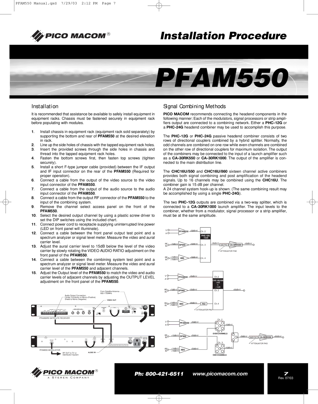
Signal Combining Methods
PICO MACOM recommends connecting the headend components in the following manner: Each of the modulators, signal processors or strip ampli- fiers output are connected to a combining network. Either a
The
The CHC16U/550 and CHC16U/860 sixteen channel active combiners provides both signal combining and post amplification of the headend signals. Up to 16 channels may be combined using the CHC16U. The combiner gain is 15 dB per channel.
A 24 channel system
The two
V |
|
| +52dBmV | Ch. 2 |
|
|
| |
| PFAM550 |
|
|
| ||||
A |
|
|
|
|
|
|
|
|
|
|
|
|
|
|
| ||
|
|
|
|
|
|
|
| |
|
|
|
|
|
|
|
| |
RF | +10dBmV SP860 | +52dBmV |
| +36dBmV |
|
| +60dBmV | |
Ch. 3 | 6dB PAD |
| ||||||
IN |
|
|
|
|
|
|
|
|
|
|
|
|
| ATTENUATOR PAD | |||
|
|
|
|
|
| |||
RF | +14dBmV | XBS | +52dBmV | Ch. 4 |
|
|
| |
IN | +10dBmV |
|
|
|
| |||
|
|
|
|
|
|
| ||
15. Adjust the Output level of the PFAM550 to match the video and audio carrier levels of adjacent channels by adjusting the OUTPUT LEVEL adjustment on the front panel of the PFAM550.
From Satellite Antenna
Audio Output Connection: |
|
Center Conductor to Mono+(Positive) |
|
Shield to | VIDEO OUT |
|
+ |
|
|
|
|
|
|
|
|
|
|
| + |
|
|
| + |
|
|
|
| + |
|
|
|
|
|
|
|
|
|
|
|
|
|
|
| VIDEO | COMPOSITE | 70 MHz | RF IN | 18V 250mA | AC25OV | FUSE | ||
|
|
|
|
|
|
|
|
|
|
|
| AUDIO OUTPUT LEVEL | OUT | OUT |
| 1/2A |
| |||||
|
|
| LANGUAGE |
| AUDIO OUTPUT |
|
|
|
|
|
| MHz | LNB POWER |
| ||||||||
|
|
|
|
|
|
|
|
| VIDEO |
|
|
|
|
| OUT |
|
| |||||
DATA | CLOCK |
| MONO | LEFT | RIGHT |
|
|
|
|
|
|
|
|
|
|
| ||||||
+ | _ | + | _ | GND | + | _ | + | _ | + | _ | L | R | MONO | LEVEL |
|
|
|
|
|
| 117V |
|
|
|
|
|
|
|
|
|
|
|
|
|
|
|
|
| IN |
|
|
|
|
| |
|
|
|
|
|
|
|
|
|
|
|
|
|
|
|
| OUT |
| ON | OFF | .35A |
| |
|
|
|
|
|
|
|
|
|
|
|
|
|
| INV | NOR |
| H | V |
|
| 60Hz |
|
|
|
|
|
|
|
|
|
|
|
|
|
|
|
|
|
|
|
|
|
| ||
PR4200IRD SATELLITE RECEIVER
VPFAM550 +55dBmV
A
RF | +10dBmV SP860 | +55dBmV |
| |
IN |
|
|
|
|
RF | +14dBmV | XBS | +60dBmV | PAD |
IN | +10dBmV |
| ||
ATTENUATOR PAD
Ch. 2
CHC-16U/550
+6dB to +12dB
Ch. 3
Ch. 4
Ch. 2
+65dBmV
|
|
|
| 125VAC | 600W MAX | AC117V |
IF IN | IF OUT | VIDEO IN | AUDIO IN | 0.5A |
| 60Hz/35W |
RF OUT |
|
|
|
|
|
|
|
|
|
| FUSE |
|
|
CAUTION: FOR CONTINUED PROTECTION AGAINST FIRE
HAZARD, REPLACE ONLY WITH SAME TYPE 0.5A 125V FUSE
PFAM550 MODULATOR
RF OUT to TV or | AUDIO IN |
Distribution System |
|
VPFAM550 +50dBmV
A |
|
|
| +43dBmV |
|
|
|
| Ch. 4 |
RF | +10dBmV SP860 | +50dBmV | EVEN CHANNELS | |
+39dBmV | ||||
IN |
|
|
|
|
|
|
|
| Ch. 3 |
RF | +14dBmV | XBS | +50dBmV | +43dBmV |
| ||||
IN | +10dBmV |
|
|
|
ODD CHANNELS
8dB PAD ![]()
![]()
ATTENUATOR PAD
+60dBmV
Ph: | 7 |
Rev. 07/03