1 |
| 2 |
|
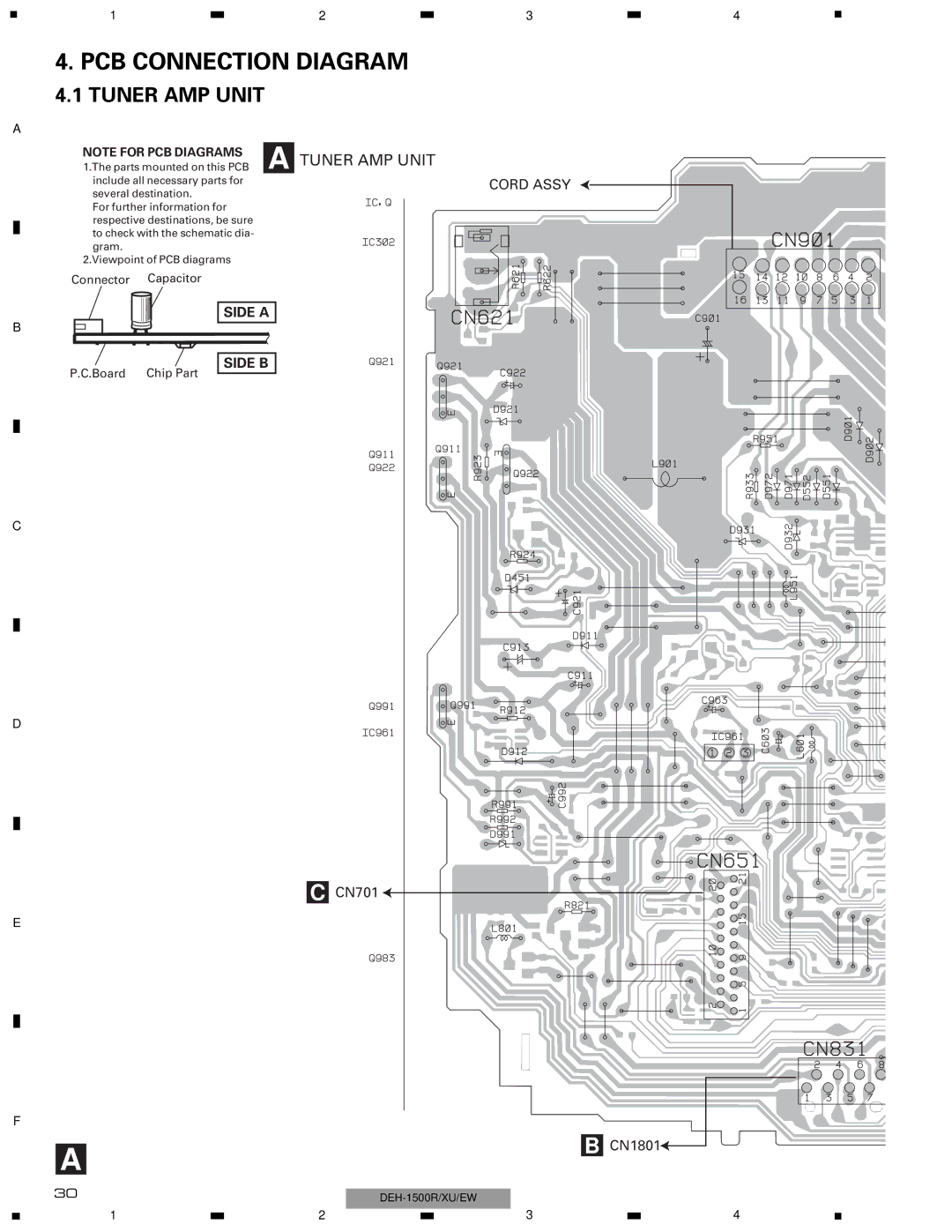
4. PCB CONNECTION DIAGRAM
4.1 TUNER AMP UNIT
A
NOTE FOR PCB DIAGRAMS | A | TUNER AMP UNIT |
1.The parts mounted on this PCB | ||
include all necessary parts for |
|
|
several destination. |
|
|
For further information for |
|
|
respective destinations, be sure |
|
|
to check with the schematic dia- |
|
|
gram. |
|
|
2.Viewpoint of PCB diagrams |
|
|
Connector Capacitor
SIDE A
B
SIDE B
P.C.Board | Chip Part |
C
D
C CN701 ![]()
E
3 |
| 4 |
|
CORD ASSY
F |
|
A | B CN1801 |
| |
30 |
|
1 |
| 2 |
| 3 |
| 4 |
|
|
| ||||
|
|
|