1 |
| 2 |
| 3 |
| 4 |
|
|
|
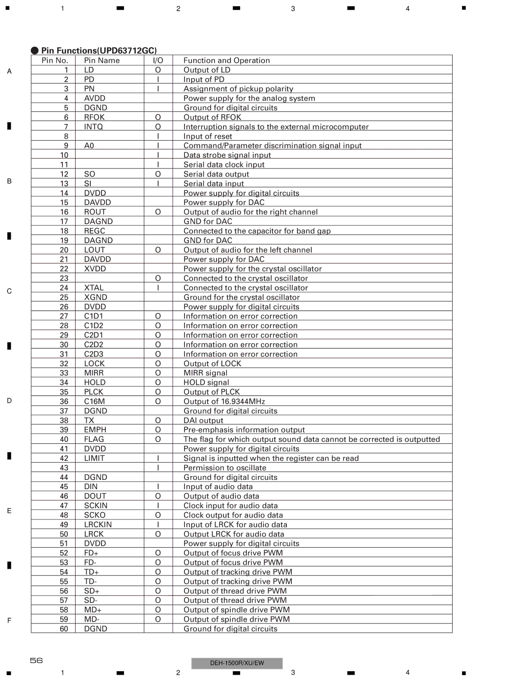
-Pin Functions(UPD63712GC)
|
|
| Pin No. | Pin Name | I/O | Function and Operation | |||
A | 1 | LD | O | Output of LD | |||||
|
| 2 | PD | I | Input of PD | ||||
|
| 3 | PN | I | Assignment of pickup polarity | ||||
|
| 4 | AVDD |
| Power supply for the analog system | ||||
|
| 5 | DGND |
| Ground for digital circuits | ||||
|
| 6 | RFOK | O | Output of RFOK | ||||
|
| 7 | INTQ | O | Interruption signals to the external microcomputer | ||||
|
| 8 | rst | I | Input of reset | ||||
|
| 9 | A0 | I | Command/Parameter discrimination signal input | ||||
|
| 10 | stb | I | Data strobe signal input | ||||
|
| 11 | sck | I | Serial data clock input | ||||
B | 12 | SO | O | Serial data output | |||||
13 | SI | I | Serial data input | ||||||
|
| 14 | DVDD |
| Power supply for digital circuits | ||||
|
| 15 | DAVDD |
| Power supply for DAC | ||||
|
| 16 | ROUT | O | Output of audio for the right channel | ||||
|
| 17 | DAGND |
| GND for DAC | ||||
|
| 18 | REGC |
| Connected to the capacitor for band gap | ||||
|
|
| |||||||
|
| 19 | DAGND |
| GND for DAC | ||||
|
|
| |||||||
|
| 20 | LOUT | O | Output of audio for the left channel | ||||
|
| 21 | DAVDD |
| Power supply for DAC | ||||
|
| 22 | XVDD |
| Power supply for the crystal oscillator | ||||
|
| 23 | xtal | O | Connected to the crystal oscillator | ||||
C | 24 | XTAL | I | Connected to the crystal oscillator | |||||
25 | XGND |
| Ground for the crystal oscillator | ||||||
|
|
| |||||||
|
| 26 | DVDD |
| Power supply for digital circuits | ||||
|
| 27 | C1D1 | O | Information on error correction | ||||
|
| 28 | C1D2 | O | Information on error correction | ||||
|
| 29 | C2D1 | O | Information on error correction | ||||
|
| 30 | C2D2 | O | Information on error correction | ||||
|
| ||||||||
|
| 31 | C2D3 | O | Information on error correction | ||||
|
| 32 | LOCK | O | Output of LOCK | ||||
|
| 33 | MIRR | O | MIRR signal | ||||
|
| 34 | HOLD | O | HOLD signal | ||||
|
| 35 | PLCK | O | Output of PLCK | ||||
D | 36 | C16M | O | Output of 16.9344MHz | |||||
|
| 37 | DGND |
| Ground for digital circuits | ||||
|
| 38 | TX | O | DAI output | ||||
|
| 39 | EMPH | O | |||||
|
| 40 | FLAG | O | The flag for which output sound data cannot be corrected is outputted | ||||
|
| 41 | DVDD |
| Power supply for digital circuits | ||||
|
| 42 | LIMIT | I | Signal is inputted when the register can be read | ||||
|
| ||||||||
|
| 43 | xtalen | I | Permission to oscillate | ||||
|
| 44 | DGND |
| Ground for digital circuits | ||||
|
| 45 | DIN | I | Input of audio data | ||||
|
| 46 | DOUT | O | Output of audio data | ||||
E | 47 | SCKIN | I | Clock input for audio data | |||||
48 | SCKO | O | Clock output for audio data | ||||||
|
| ||||||||
|
| 49 | LRCKIN | I | Input of LRCK for audio data | ||||
|
| 50 | LRCK | O | Output LRCK for audio data | ||||
|
| 51 | DVDD |
| Power supply for digital circuits | ||||
|
| 52 | FD+ | O | Output of focus drive PWM | ||||
|
| 53 | FD- | O | Output of focus drive PWM | ||||
|
| ||||||||
|
| 54 | TD+ | O | Output of tracking drive PWM | ||||
|
|
| 55 | TD- | O | Output of tracking drive PWM | |||
|
| 56 | SD+ | O | Output of thread drive PWM | ||||
|
| 57 | SD- | O | Output of thread drive PWM | ||||
|
| 58 | MD+ | O | Output of spindle drive PWM | ||||
F |
| 59 | MD- | O | Output of spindle drive PWM | ||||
|
| 60 | DGND |
| Ground for digital circuits | ||||
|
| 56 |
|
|
|
| |||
|
|
|
|
|
|
| |||
|
|
|
|
|
|
|
|
| |
1 |
| 2 |
| 3 |
| 4 |
|
|
| ||||
|
|
|