5 |
| 6 |
| 7 |
| 8 |
|
|
|
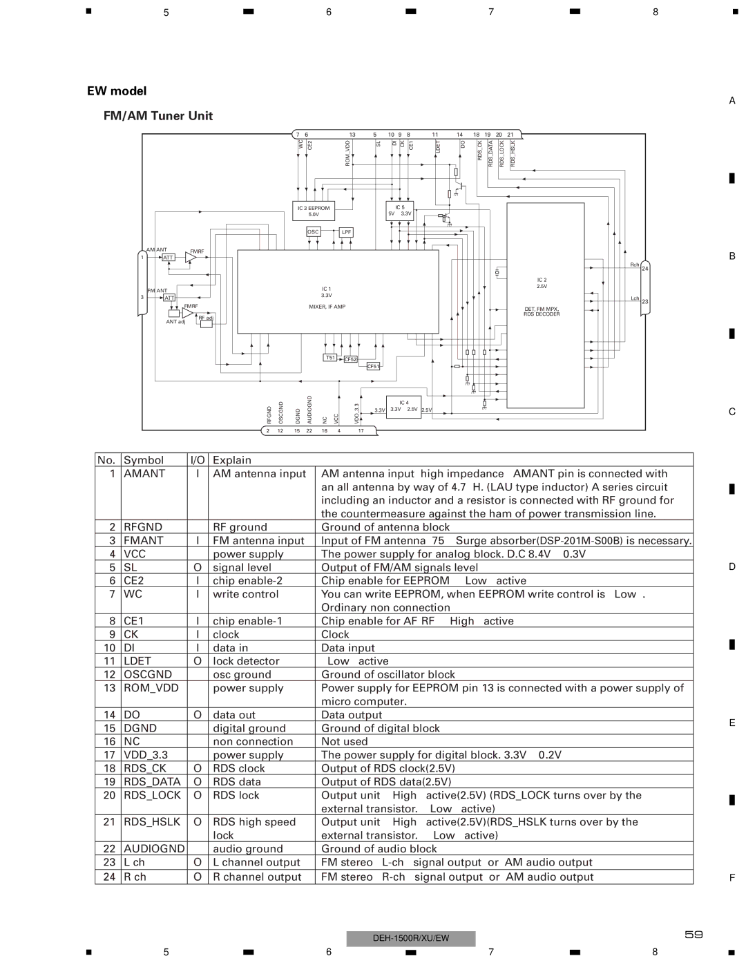
EW model
-FM/AM Tuner Unit
A
| AM ANT | FMRF |
1 | ATT |
|
7 6
WC | CE2 |
IC 3 EEPROM
5.0V
OSC
13 | 5 | 10 | 9 | 8 | 11 |
|
|
|
| 14 | 18 | 19 | 20 | |||||||
ROM VDD |
| SL | DI | CK | CE1 | LDET |
|
|
|
| DO | RDS CK | RDS DATA | RDS LOCK | ||||||
|
|
|
|
|
|
|
|
|
|
|
|
|
|
|
|
|
|
|
|
|
|
|
|
|
|
|
|
|
|
|
|
|
|
|
|
|
|
|
|
|
|
|
|
|
|
|
|
|
|
|
|
|
|
|
|
|
|
|
|
|
|
|
|
|
|
|
|
|
|
|
|
|
|
|
|
|
|
|
|
|
|
| |
|
|
|
|
|
|
|
|
|
|
|
|
|
|
|
|
|
|
|
|
|
|
|
|
|
|
|
|
|
|
|
|
|
|
|
|
|
|
|
|
| |
|
|
|
| IC 5 |
|
|
|
|
|
|
|
|
|
|
|
|
|
|
| |
|
|
|
| 5V | ← 3.3V |
|
|
|
|
|
|
|
|
|
|
|
|
|
| |
|
|
|
|
|
|
|
|
|
|
|
|
|
|
|
|
|
|
|
|
|
LPF |
|
|
|
|
|
|
|
|
|
|
|
|
|
|
|
|
|
|
|
|
|
|
|
|
|
|
|
|
|
|
|
|
|
|
|
|
|
|
|
|
|
|
|
|
|
|
|
|
|
|
|
|
|
|
|
|
|
|
|
|
|
|
21
RDS_HSLK
IC 2
Rch 24
B
FM ANT
3![]() ATT
ATT ![]()
![]()
![]()
![]() FMRF
FMRF
RF adj
ANT adj
IC 1
3.3V
MIXER, IF AMP
|
|
|
|
|
|
|
|
|
|
|
|
|
|
|
|
|
|
|
|
|
|
|
|
|
|
| T51 |
| CF52 |
|
|
|
|
|
| ||
|
|
|
|
|
|
|
|
|
|
|
|
|
|
|
|
|
|
|
|
|
|
|
|
|
|
|
|
|
|
|
|
| CF51 |
|
|
|
|
|
|
|
|
|
| AUDIOGND |
|
|
|
|
|
|
|
|
|
|
|
|
|
| RFGND | OSCGND | DGND | NC | VCC |
| _3.3VDD |
|
|
|
|
| |||||
|
|
|
|
| IC 4 |
| ||||||||||||
|
|
|
|
|
|
|
|
|
|
|
|
|
| 3.3V | 3.3V | ← 2.5V | 2.5V | |
| 2 | 12 | 15 | 22 | 16 | 4 | 17 |
|
|
|
|
| ||||||
|
|
|
|
|
| |||||||||||||
2.5V
DET, FM MPX,
RDS DECODER
Lch 23
C
No. | Symbol | I/O | Explain |
|
|
|
|
|
1 | AMANT | I | AM antenna input | AM antenna input high impedance AMANT pin is connected with |
| |||
|
|
|
| an all antenna by way of 4.7∝ H. (LAU type inductor) A series circuit |
| |||
|
|
|
| including an inductor and a resistor is connected with RF ground for |
| |||
|
|
|
| the countermeasure against the ham of power transmission line. |
| |||
2 | RFGND |
| RF ground | Ground of antenna block |
|
|
| |
3 | FMANT | I | FM antenna input | Input of FM antenna 75Ω Surge |
| |||
4 | VCC |
| power supply | The power supply for analog block. D.C 8.4V ± 0.3V |
| |||
5 | SL | O | signal level | Output of FM/AM signals level |
| |||
6 | CE2 | I | chip | Chip enable for EEPROM | ” Low” active |
| ||
7 | WC | I | write control | You can write EEPROM, when EEPROM write control is “ Low” . |
| |||
|
|
|
| Ordinary non connection |
|
|
| |
8 | CE1 | I | chip | Chip enable for AF•RF ” High” active |
| |||
9 | CK | I | clock | Clock |
|
|
| |
10 | DI | I | data in | Data input |
|
|
| |
11 | LDET | O | lock detector | “ Low” active |
|
|
| |
12 | OSCGND |
| osc ground | Ground of oscillator block |
|
|
| |
13 | ROM_VDD |
| power supply | Power supply for EEPROM pin 13 is connected with a power supply of |
| |||
|
|
|
| micro computer. |
|
|
| |
14 | DO | O | data out | Data output |
|
|
| |
15 | DGND |
| digital ground | Ground of digital block |
|
|
| |
16 | NC |
| non connection | Not used |
|
|
| |
17 | VDD_3.3 |
| power supply | The power supply for digital block. 3.3V ± 0.2V |
| |||
18 | RDS_CK | O | RDS clock | Output of RDS clock(2.5V) |
|
|
| |
19 | RDS_DATA | O | RDS data | Output of RDS data(2.5V) |
|
|
| |
20 | RDS_LOCK | O | RDS lock | Output unit “ High” active(2.5V) (RDS_LOCK turns over by the |
| |||
|
|
|
| external transistor. “ Low” active) |
| |||
21 | RDS_HSLK | O | RDS high speed | Output unit “ High” active(2.5V)(RDS_HSLK turns over by the |
| |||
|
|
| lock | external transistor. “ Low” | active) |
| ||
22 | AUDIOGND |
| audio ground | Ground of audio block |
|
|
| |
23 | L ch | O | L channel output | FM stereo “ |
| |||
24 | R ch | O | R channel output | FM stereo “ |
| |||
|
|
|
|
|
|
| 59 | |
|
|
|
|
|
|
| ||
|
|
|
|
|
|
|
|
|
D
E
F
5 |
| 6 |
| 7 |
| 8 |
|
|
| ||||
|
|
|