Connections
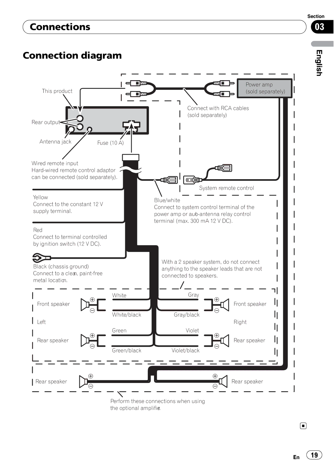
Connection diagram
Section
03
English
This product |
|
Rear output |
|
Antenna jack | Fuse (10 A) |
Wired remote input |
can be connected (sold separately). |
Yellow
Connect to the constant 12 V supply terminal.
Red
Connect to terminal controlled by ignition switch (12 V DC).
Power amp (sold separately)
Connect with RCA cables (sold separately)
System remote control
Blue/white
Connect to system control terminal of the power amp or
|
| With a 2 speaker system, do not connect | |
Black (chassis ground) | |||
anything to the speaker leads that are not | |||
Connect to a clean, | |||
connected to speakers. | |||
metal location. | |||
| |||
Front speaker
Left
Rear speaker
White | Gray |
Front speaker
White/blackGray/black
Right
Green | Violet |
Rear speaker
Green/blackViolet/black
Rear speaker | Rear speaker |
Perform these connections when using the optional amplifier.
En ![]() 19
19![]()