Connecting the Units
<ENGLISH>
Note:
• This unit is for vehicles with a |
negative grounding. Before installing it in a recre- |
ational vehicle, truck, or bus, check the battery |
voltage. |
• To avoid shorts in the electrical system, be sure to |
disconnect the ≠ battery cable before beginning |
• When this product’s source is switched ON, a con- |
trol signal is output through the blue/white lead. |
Connect to an external power amp’s system remote |
control or the car’s |
minal (max. 300 mA 12 V DC). If the car features |
a glass antenna, connect to the antenna booster |
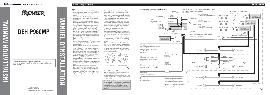
Connection diagram for standard mode
Antenna jack | 15 cm | |
|
Jack for the Wired Remote Control (WIRED REMOTE INPUT) Refer to Wired Remote Control’s manual
(sold separately).
Subwoofer output
(LOW/SUBWOOFER OUTPUT)
23 cm (9 in.)
Connecting cords with RCA pin plugs (sold separately)
Power amp (sold separately)
MANUAL
DEH-P960MP
installation. |
• Refer to the owner’s manual for details on con- |
necting the power amp and other units, then make |
connections correctly. |
• Secure the wiring with cable clamps or adhesive |
tape. To protect the wiring, wrap adhesive tape |
around them where they lie against metal parts. |
• Route and secure all wiring so it cannot touch any |
moving parts, such as the gear shift, handbrake |
and seat rails. Do not route wiring in places that |
get hot, such as near the heater outlet. If the insula- |
tion of the wiring melts or gets torn, there is a dan- |
ger of the wiring |
body. |
• Don’t pass the yellow lead through a hole into the |
engine compartment to connect to the battery. This |
will damage the lead insulation and cause a very |
dangerous short. |
• Do not shorten any leads. If you do, the protection |
circuit may fail to work when it should. |
• Never feed power to other equipment by cutting |
the insulation of the power supply lead of the unit |
and tapping into the lead. The current capacity of |
the lead will be exceeded, causing overheating. |
• When replacing fuse, be sure to use only fuse of |
power supply terminal. |
• When an external power amp is being used with |
this system, be sure not to connect the blue/white |
lead to the amp’s power terminal. Likewise, do not |
connect the blue/white lead to the power terminal |
of the |
excessive current drain and malfunction. |
• To avoid |
lead with insulating tape. Especially, insulate the |
unused speaker leads without fail. There is a possi- |
bility of |
ed. |
• To prevent incorrect connection, the input side of |
the |
is black. Connect the connectors of the same colors |
correctly. |
• If this unit is installed in a vehicle that does not |
have an ACC (accessory) position on the ignition |
switch, the red lead of the unit should be connected |
to a terminal coupled with ignition switch ON/OFF |
operations. If this is not done, the vehicle battery |
may be drained when you are away from the vehi- |
cle for several hours. (Fig. 1) |
DSP switch
Switch the DSP switch This product as illustration below.
15 cm
![]()
Yellow/black
If you use a cellular telephone, connect it via the Audio Mute lead on the cellular telephone. If not, keep the Audio Mute lead free of any connections.
Rear output
(MID/REAR OUTPUT) ![]() 15 cm
15 cm
Front output
(HIGH/FRONT OUTPUT)
Blue/white
To system control terminal of the power amp or
+
Front speaker
≠
Power amp (sold separately)
Power amp (sold separately)
System remote control
+
Front speaker
≠
INSTALLATION
This product conforms to CEMA cord colors.
Le code de couleur des câbles utilisé pour ce produit est con- forme à CEMA.
MANUEL D’INSTALLATION
the rating prescribed on the fuse holder. |
• Since a unique BPTL circuit is employed, never |
wire so the speaker leads are directly grounded or |
the left and right ≠ speaker leads are common. |
• If the RCA pin jack on the unit will not be used, do |
not remove the caps attached to the end of the con- |
nector. |
• Speakers connected to this unit must be high- |
power types with minimum rating of 50 W and |
impedance of 4 to 8 ohms. Connecting speakers |
with output and/or impedance values other than |
those noted here may result in the speakers catch- |
ing fire, emitting smoke, or becoming damaged. |
|
| CC |
|
|
|
|
|
|
|
|
| F | A | O |
|
|
| F | O |
|
|
|
| N |
| N | ||||||
O | F |
|
|
|
| O | F |
|
|
|
|
|
|
| S |
|
|
| S | ||
|
|
|
|
|
|
|
|
| ||
|
|
|
|
| T |
|
|
|
| T |
|
|
|
| R | A |
|
|
| R | A |
|
|
| T |
|
|
| T |
| ||
ACC position | No ACC position | |||||||||
Fig. 1
• The black lead is ground. Please ground this lead |
separately from the ground of |
ucts such as power amps. |
If you ground the products together and the ground |
Yellow
To terminal always supplied with power regardless of ignition switch position.
Red
To electric terminal controlled by ignition switch (12 V DC) ON/OFF.
Orange/white
To lighting switch terminal.
Fuse holder
Fuse resistor
Fuse resistor
Front speaker
Left
Rear speaker
White
+
≠
White/black
Green
+
≠
Green/black
Gray
+
≠
Gray/black
Violet
+
≠
Violet/black
Front speaker
Right
Rear speaker
Printed in Thailand
becomes detached, there is a risk of damage to the |
products or fire. |
• Cords for this product and those for other products |
may be different colors even if they have the same |
function. When connecting this product to another |
product, refer to the supplied manuals of both |
products and connect cords that have the same |
Black (ground)
To vehicle (metal) body.
With a 2 speaker system, do not connect anything to the speaker leads that are not connected to speakers.
Perform these connections when using the optional amplifier.
+ | + |
Rear speaker |
|
≠ | ≠ |
+ | + |
Subwoofer |
|
≠ | ≠ |
Rear speaker
Subwoofer
Imprimé en Thaïlande
function.
Fig. 2