Installation | <ENGLISH> | |
DIN |
| Switching the DSP setting mode |
Installation using the screw holes on the side of the unit
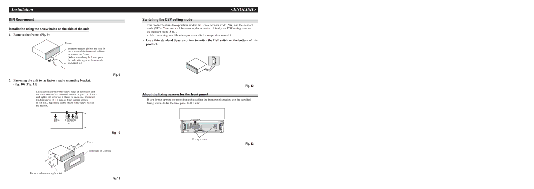
1. Remove the frame. (Fig. 9)
Frame
Insert the release pin into the hole in the bottom of the frame and pull out to remove the frame.
(When reattaching the frame, point the side with a groove downwards and attach it.)
This product features two operation modes: the
•After switching, reset the microprocessor. (Refer to operation manual.)
•Use a thin standard tip screwdriver to switch the DSP switch on the bottom of this product.
Fig. 9
2.Fastening the unit to the factory radio mounting bracket. (Fig. 10) (Fig. 11)
Select a position where the screw holes of the bracket and the screw holes of the head unit become aligned (are fitted), and tighten the screws at 2 places on each side. Use either binding screws (5 ⋅ 6 mm) or flush surface screws
(5 ⋅ 6 mm), depending on the shape of the screw holes in the bracket.
Fig. 12
About the fixing screws for the front panel
If you do not operate the removing and attaching the front panel function, use the supplied fixing screws to fix the front panel to this unit.
Fig. 10
Fixing screws
Screw
Fig. 13
Dashboard or Console
Factory radio mounting bracket
Fig.11