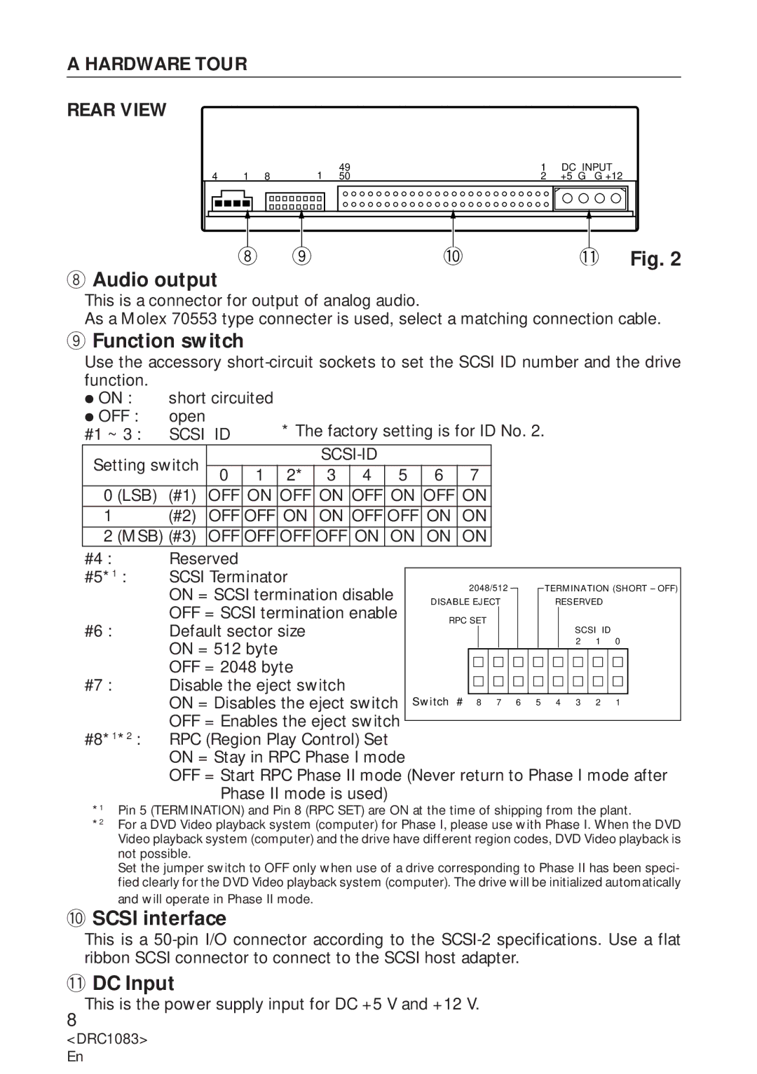
A HARDWARE TOUR
REAR VIEW
4 | 1 | 8 | 1 | 49 | 1 | DC INPUT |
50 | 2 | +5 G G +12 |
8 9 | 0 | - Fig. 2 |
8Audio output
This is a connector for output of analog audio.
As a Molex 70553 type connecter is used, select a matching connection cable.
9Function switch
Use the accessory
ÖON : short circuited
ÖOFF : open
#1 ~ 3 : | SCSI | ID |
|
| * The factory setting is for ID No. 2. |
|
|
|
|
|
|
| |||||||||||||
Setting switch |
|
|
|
|
|
|
|
|
|
|
|
|
|
|
|
|
|
|
|
| |||||
0 | 1 |
| 2* | 3 | 4 |
| 5 | 6 |
| 7 |
|
|
|
|
|
|
|
|
| ||||||
|
|
|
|
|
|
|
|
|
|
|
|
|
|
| |||||||||||
0 (LSB) | (#1) | OFF | ON | OFF | ON | OFF | ON | OFF | ON |
|
|
|
|
|
|
|
|
| |||||||
1 |
| (#2) | OFF | OFF | ON | ON | OFF | OFF | ON | ON |
|
|
|
|
|
|
|
|
| ||||||
2 (MSB) (#3) | OFF | OFF | OFF | OFF | ON | ON | ON |
| ON |
|
|
|
|
|
|
|
|
| |||||||
#4 : |
| Reserved |
|
|
|
|
|
|
|
|
|
|
|
|
|
|
|
|
|
|
|
|
|
| |
#5*1 : | SCSI Terminator |
|
|
|
|
|
| 2048/512 |
| TERMINATION (SHORT – OFF) | |||||||||||||||
|
| ON = SCSI termination disable |
|
|
|
| |||||||||||||||||||
|
|
|
| DISABLE EJECT |
| RESERVED | |||||||||||||||||||
|
| OFF = SCSI termination enable |
|
|
| ||||||||||||||||||||
|
|
|
| RPC SET |
|
|
|
|
|
|
| ||||||||||||||
#6 : |
| Default sector size |
|
|
|
|
|
|
| SCSI | ID | ||||||||||||||
|
|
|
|
|
|
|
|
|
|
|
|
|
|
| |||||||||||
|
| ON = 512 byte |
|
|
|
|
|
|
|
|
|
|
|
|
| 2 | 1 | 0 |
| ||||||
|
|
|
|
|
|
|
|
|
|
|
|
|
|
|
|
|
|
|
|
|
| ||||
|
| OFF = 2048 byte |
|
|
|
|
|
|
|
|
|
|
|
|
|
|
|
|
|
|
| ||||
#7 : |
| Disable the eject switch |
|
|
|
|
|
|
|
|
|
|
|
|
|
|
|
|
|
| |||||
|
| ON = Disables the eject switch |
| Switch | # 8 7 6 5 | 4 3 | 2 | 1 |
| ||||||||||||||||
|
| OFF = Enables the eject switch |
|
|
|
|
|
|
|
|
|
|
|
|
|
|
| ||||||||
|
|
|
|
|
|
|
|
|
|
|
|
|
|
|
|
| |||||||||
#8*1*2 : | RPC (Region Play Control) Set |
|
|
|
|
|
|
|
|
|
|
|
|
|
|
|
| ||||||||
|
| ON = Stay in RPC Phase I mode |
|
|
|
|
|
|
|
|
|
|
|
|
|
| |||||||||
|
| OFF = Start RPC Phase II mode (Never return to Phase I mode after | |||||||||||||||||||||||
|
|
| Phase II mode is used) |
|
|
|
|
|
|
|
|
|
|
|
|
|
|
|
| ||||||
*1 | Pin 5 (TERMINATION) and Pin 8 (RPC SET) are ON at the time of shipping from the plant. | ||||||||||||||||||||||||
*2 | For a DVD Video playback system (computer) for Phase I, please use with Phase I. When the DVD | ||||||||||||||||||||||||
| Video playback system (computer) and the drive have different region codes, DVD Video playback is | ||||||||||||||||||||||||
| not possible. |
|
|
|
|
|
|
|
|
|
|
|
|
|
|
|
|
|
|
|
|
|
|
| |
Set the jumper switch to OFF only when use of a drive corresponding to Phase II has been speci- fied clearly for the DVD Video playback system (computer). The drive will be initialized automatically
and will operate in Phase II mode.
0SCSI interface
This is a
-DC Input
This is the power supply input for DC +5 V and +12 V.
8
<DRC1083> En
